A Guide to High-Voltage DC Field Testing
A Guide to High-Voltage DC Field Testing
In 1996, the insulated conductor industry determined that DC-withstand testing of the plastic (XLPE) insulation systems, either in the cable factory as a routine production test or after installation as the higher voltage proof test, was detrimental to the life of the insulation and therefore stopped recommending it. Medium voltage EPR insulating systems are not subject to the same aging characteristics, however, and can be DC-tested as required in accordance with the tables below.
High-Voltage DC Field Testing
When an insulated cable arrives on the job site, the recipient should be able to confidently assume it will attain the designed service life. This means it must arrive free of internal discontinuities in the dielectric, such as voids or inclusions, as well as air pockets at the interfaces between the shielding systems and the dielectric’s surfaces. It is, however, the specter of mechanical damage, or substandard splicing and terminating, that could cause engineers to desire a field-applied proof test to establish the cable’s serviceability and predict continuity of service.
The time-honored methods of proof testing in the field involve high potential direct current (DC). The advantage of the DC test is obvious; since the DC potential does not produce harmful discharge as readily as the AC, it can be applied at higher levels without risk of damaging good insulation. This higher potential can literally “sweep-out” far more local defects. The simple series circuit path of a local defect is more easily carbonized or reduced in resistance by the DC leakage current than by AC, and the lower the fault path resistance becomes, the more the leakage current increases, thus producing a snowball effect, which leads to the small visible dielectric puncture usually observed. Since the DC is free of capacitive division, it is more effective in picking out mechanical damage as well as inclusions or areas in the dielectric that have lower resistance.
Field tests should be utilized to assure freedom from electrical weakness in the circuit caused by such things as mechanical damage and unexpected environmental factors. Field tests should not be used to seek out minute internal discontinuities in the dielectric or faulty shielding systems, all of which should have been eliminated at the factory, nor should the DC potential be so excessive that it would initiate punctures in otherwise good insulation.
For low-voltage power and control cables, it is general practice to use a megger for checking the reliability of the circuit. This essentially means measuring the insulation resistance of the circuit to determine whether or not it is high enough for satisfactory operation. For higher-voltage cables, the megger is not usually sufficient and the use of high-voltage testing equipment is more common. Even at the lower voltages, high voltage DC tests are increasingly favored. The use of high-voltage DC has many advantages over other types of testing procedures.
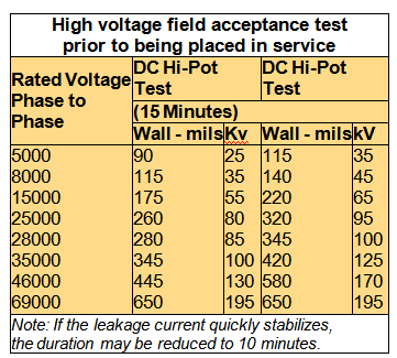
DC Field Acceptance Testing
It is general practice, and obviously empirical, to relate the field test voltage upon installation to the final factory-applied DC potentials by using a factor of 80%. The final factory-test voltages can be found in the appropriate industry specifications. This means that prior to being connected to other equipment, solid extruded dielectric-insulated, shielded cables rated 5kV and up may be given a field acceptance test of about 300 volts per mil. The actual test values recommended for the field acceptance test are presented in the table below. If other equipment is connected, it may limit the test voltage, making considerably lower levels more compatible with the complete system.
Test Limitations
The DC leakage can be affected by external factors, such as heat, humidity, wind, and water level if unshielded and in ducts or conduits, and by internal heating if the cable under test has recently been heavily loaded. These factors make comparisons of periodic data obtained under different test conditions very difficult. If other equipment is connected into the cable circuit, this makes it even more difficult. In the event hot-poured, compound-filled splices and terminations are involved, testing should not be performed until they have cooled to room temperature.
The relays in high-voltage DC test equipment are usually set to operate with 5 to 25 milliamperes leakage. In practice, the shape of the leakage curve, assuming constant voltage, is more important than either the absolute leakage current of a “go or no-go” withstand test result.
Test Notes
From the standpoint of safety as well as data interpretation, only qualified personnel should run these high voltage tests. After the voltage has been applied and the test level reached, the leakage current may be recorded at one-minute intervals. As long as the leakage current decreases or stays steady after it has leveled off, the cable is considered satisfactory. If the leakage current starts to increase, excluding momentary spurts due to supply-circuit disturbances, trouble may be developing and the test may be extended to see if the rising trend continues. The end point is, of course, the ultimate breakdown. This is manifested by an abrupt increase in the magnitude of the leakage current and a decrease in the test voltage. It should result in relay action to “trip” the set off the line, but this assumes the equipment has enough power to maintain the test voltage and supply the normal test current.
Since the total current required is a function of cable capacity, condition of dielectric, temperature, end leakage, and length, the test engineer must be sure that “relay action” actually signifies a local fault rather than being merely an indication that the voltage had been applied too quickly or one of the other factors contributing to the total current had been the cause.
At the conclusion of each test, the discharge and grounding of the circuit requires the attention of a qualified test engineer to prevent damage to the insulation and injury to personnel.
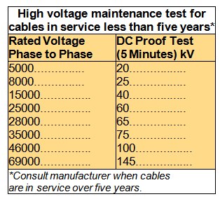
Maintenance Proof Testing
It may be justifiable in the case of important circuits to make periodic tests during the life of the installation to determine whether or not there has been significant deterioration due to severe and perhaps unforeseen operational or environmental conditions. The advantage of a scheduled proof test is, of course, that it can frequently “anticipate” a future service failure, and the necessary repair or renewal can be made without a service interruption, usually during a major shutdown.
Furthermore, a DC test failure is seldom burned-out, and visual analysis may disclose the cause and permit corrective action.
As a note of caution: Once a complete circuit has been connected and all exposed ends sealed, it is not desirable when maintenance proof-testing to remove these seals and disconnect the conductors. It is sometimes impossible to provide “ends” with adequate clearance and length of insulation surface to permit high-voltage testing, even at the levels specified in the following table. Further, there is the danger of mechanically injuring the dielectric during the seal removal and end preparation. This is a major reason why a megger test is often used in maintenance checking of the numerous circuits in a power plant.
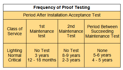
Frequency of Tests
In the case of power plants, it is customary to schedule desired maintenance proof tests to coincide with planned major shutdowns. It is not necessary or justifiable to check every circuit each year. The following schedule is suggested as a guide.
* Visit Okonite online to read this white paper and learn more about high-voltage proof design.
- Facts & Figures: Semiconductor Market Grew to a Record $336 Billion - March 2, 2015
- TLC and Metz Ethernet Cat 6A Patch Cords in Seven Vibrant Colors - January 27, 2014
- Cables Unlimited LC-LC Duplex Ruggedized Fiber Jumpers - January 27, 2014