Acceleration Factors and Connector Testing
Dr Bob on Acceleration Factors and Connector Testing
The first article in this series on connector testing programs, “The How and Why of Connector Testing,” included the following comments:
Moving to “why,” there are several reasons for testing connectors. They include:
- Design verification
- Qualification/specification
- Performance verification
- Reliability assessment
Each of these purposes uses the same basic test groups and procedures. Where they differ, is in the details of the conditioning procedures and the selected exposures—both the severity and duration of the exposures. The key concern in exposure severity and duration is to define the relationship between the exposure and the intended application environment of the connector. In addition, the requirements for “passing” the test will be different for each purpose. This discussion will continue in detail after a complete review of a generic testing program has been completed in future articles in this series.
The “review of a generic testing program,” based on EIE 364D, is complete. So it is now time to discuss issues relating to exposure severity and duration as they relate to the testing purposes listed above, particularly in performance verification and reliability assessment. These two testing purposes share a common requirement with respect to exposure severity and duration: the relationship between the exposure severity and duration during testing and its lifetime in the field must be “known.” The quotation marks around the word “known” are intended to indicate that, in general, the relationship is not known. The task, then, is to define a rationale for determining or approximating that relationship. In other words, an “acceleration factor” between the severity/duration of the test conditions and lifetime in the field must be established.
The importance of this relationship was first raised in the article, “Comparison and Performance: EIA 364D Test Group 2,” in the following comment:
Consideration of Test Group 2 of the generic test sequence of EIA 364D has highlighted some of the important issues relating to the purpose of testing. Two purposes have been identified in this discussion, comparative testing and performance assessment. In a comparative assessment, a standardized sequence using standard conditioning, that is, for example, a prescribed number of thermal shock cycles at given values of temperature range and dwell times, is relevant. If the purpose of testing is performance assessment, the conditioning—or in this case what I call exposure—parameters must be tailored to represent the conditions expected in the specific application under consideration. While the selection of the exposure severity and duration parameters is “arbitrary,” the rationale for those parameters must be grounded in a considered assessment of the application conditions and expected life of the connector in the field.
To begin the discussion, consider an acceleration factor for durability testing. If a connector has an intended life 10-year field life, including a durability life of 500 mating cycles, the connector can simply be mated and unmated 500 times. The acceleration factor uses time compression: the 500 cycles can be completed in less than two hours. This, of course, does not directly simulate field conditions, where the mating cycles will be randomly distributed with variable times between mating cycles, but this difference is not expected to affect the durability performance.
The complexity of acceleration factor determination increases when mechanical stability testing, through thermal or mechanical shock exposures, is considered. The important issue here is determining the number of exposure cycles, under what conditions, represent an appropriate simulation of the intended field life. These determinations are application-dependent with respect to both number of cycles and stimulating conditions. Simulation of thermal driving forces is relatively straightforward. The temperature range and rate of temperature change during testing control those forces and can be simulated directly in the testing conditions. The details of those parameters, however, must be determined by consideration of the thermal conditions appropriate to the intended application. Mechanical driving forces are more variable and complex and, thus, the simulation or test conditions may be more difficult to define. In addition to the magnitude and rate of application of mechanical forces, the direction of application may also be a significant variable. Similar comments apply to vibration testing, with the additional concern that the frequency of vibration may also be significant if it corresponds to a resonant frequency in the mechanical mounting of the connector. To summarize, simulation of these types of driving forces by appropriate test procedures is readily accomplished in most cases. The difficulty is in defining which parameters of the field application driving forces to apply in the test exposure so that an acceleration factor can be developed.
Temperature-life testing, or heat aging, to stimulate stress relaxation effects on performance, raises different issues. As mentioned in a previous article, “Test Group 5: Stress Relaxation,” stress relaxation results in a loss in contact normal force due to thermally-driven atomic rearrangements to reduce localized stresses, which, in turn, results in a change in the shape of the contact spring. For example, the gap between two tines of a twin-beam contact will increase due to stress relaxation, which effectively reduces the contact deflection, and, thus, the contact force. Simulation of the driving forces for stress relaxation is straightforward. The temperature and duration of the exposure are the significant variables, and these parameters must be determined from an evaluation of the relevant application conditions, in this case, the temperature profile of the intended application. An acceleration factor for simulation of stress relaxation is available, though material dependent, from experimental data. But, as also mentioned in the referenced article, the effect of stress relaxation on performance is not as straightforward. It’s dependent on the reduction in mechanical stability that results from the loss in contact force. The significance of the reduction depends, in turn, on the magnitude of the initial contact normal force.
Now consider the effects of corrosion on connector performance. As discussed in the previous series on connector degradation mechanisms, there are two different corrosion mechanisms active in connectors: fretting corrosion (for tin-plated contact systems) and general corrosion (for gold-plated contact systems). As noted in the degradation mechanism series, gold does not corrode. Corrosion comes from exposed copper base metal from the contact spring system, due to factors such as wear or porosity.
Fretting corrosion degradation results from oxidation of the tin surface due to fretting micromotions and is dependent on the mechanical stability of the connector in its application environment. Thus, simulation of fretting degradation requires consideration of the issues discussed with respect to mechanical disturbances.
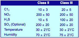
Simulation of the corrosion processes in gold-plated connectors is analogous to stress relaxation in that the corrosion processes, though complex, are consistent. During the 1970s and 80s, numerous workers generated large amounts of data relating to corrosion mechanisms in connectors exposed to a variety of field environments. The dominant corrosion mechanism in the field was found to be dependent on the concentration of certain chemical species, as mentioned in a previous article in this series, “Test Group 4: Let’s Not Be Too Harsh.” In relatively benign environments, pore corrosion was prevalent. As the concentrations of sulfur and chlorine increased, corrosion creep, migration of corrosion products from corrosion sites over the contact surface became increasingly dominant. Four different classes of environments ranging from benign (Class I), office (Class II), industrial (Class III), and harsh (Class IV) were defined by Battelle Laboratories. The table below shows components of the most commonly used test environments, which simulate field environments corresponding to Class II and Class III.
Mixed Flowing Gas
(Concentration – ppb*)
From the field data, acceleration factors for corrosion under various conditions were determined. For example, for a Class III application environment, two days in the test environment listed above correlates to one year in the field.
To summarize, acceleration factors are available, with qualifying comments, for stress relaxation and corrosion of gold-plated connector systems. Acceleration factors for fretting corrosion and mechanical driving forces are not straightforward.
Does this state of knowledge significantly affect the benefits of connector testing programs? Not necessarily. As mentioned in previous articles, comparison testing of competitive product under the same test conditions can provide meaningful discrimination between the performances of the products. A second option, when performance assessment is the objective of the testing, is to provide a rationale for approximate acceleration factors based on fundamental mechanisms or field experience. The more detailed the rationale, the more significant the interpretation of the test data in such cases. When reliability assessment is the objective, the quality of the rationale takes on additional importance and an additional factor comes into play; failure criterion, generally referenced to a change in contact resistance, must be known. Discussion of this issue is controversial and will be discussed in my next article.
Next time, Max Peel, Senior Fellow at Contech Research will provide his perspective on acceleration testing.
- Nanocrystalline Silver Alloy Contact Finishes in Electronic Applications - April 6, 2015
- Nanocrystalline Silver Contact Platings - March 16, 2015
- Dr. Bob on Gold Flash Contact Finishes (and Max Peel) - September 22, 2014


