Degradation Mechanisms – Loss in contact normal force
Degradation Mechanisms – Loss in contact normal force
In the previous article on wear as a degradation mechanism, I noted that wear is an indirect degradation mechanism. Wear of the contact finish, if it exposes the underlying base metal of the contact spring, introduces additional sources of corrosion directly at the contact interface. Similar comments apply to contact normal force. Loss in contact normal force is an indirect degradation mechanism, because it enhances the potential for micromotions of the contact interface during the application lifetime of the connector. As previously covered, micromotions, or fretting motions, can lead to fretting corrosion in tin finished systems, and fretting wear in noble finished systems. In both cases, loss in contact normal force can lead to increased susceptibility to micromotion and, therefore, to corrosion-related degradation and associated increases in contact resistance. To understand the mechanisms that can result in a loss in contact force requires understanding of how contact forces are created.
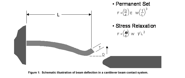
Simply stated, contact normal force is generated by the deflection of a receptacle contact beam by the plug contact as it is inserted into the receptacle, as the connector is mated. Figure 1. schematically illustrates the deflection of a simple cantilever beam receptacle contact by a post contact. Many receptacle contacts are cantilever beams or variations on cantilever beams. Two equations appropriate to cantilever beam contacts are included in Figure 1.
 Consider first Equation 1., which shows the relationship between contact force and receptacle contact beam geometry and deflection.
Equation 1.: F = (1/4) E D w (t/l)3
In Equation 1., F is the contact force, E is the elastic modulus of the base metal of the receptacle contact, D is the deflection of the receptacle contact by the plug contact, w, l, and t are the width, length, and thickness of the receptacle contact beam. Elastic modulus is a material parameter and varies with the contact material. The variation in elastic modulus over the typical range of copper alloys used in connectors is relatively small and of the order of 16-19 mpsi. For example, consider three alloys used in connectors—brass (C26000), phosphor-bronze (C51000), and beryllium-copper (C17200). The elastic modulus of these materials, respectively, is 16, 16, and 18.5 mpsi. The beam deflection, D, is a design parameter. The contact beam geometry is also a design variable. For a given set of D, w, t, and l, and the limited range of elastic modulus for copper alloys, most contacts will give a comparable contact normal force according to Equation 1.
Equation 2. illustrates a greater variance in material dependence.
Equation 2.: F = (1/6) s w (t/l2)
In Equation 2., s is the stress introduced in the contact beam by the beam deflection, and w, t, and l, are as described above. The maximum stress a beam can support without plastic, or permanent, deformation is given by the elastic limit of the material. Most materials are described in terms of the 0.2 percent offset yield strength, a value proportional to the elastic limit. The commonly used yield strengths of the example materials in connectors are of the order of 75, 95, and 110 kpsi for brass, phosphor-bronze, and beryllium-copper, respectively. These data show that, for constant geometry and deflection and elastic deformation, brass can provide a lower contact force than phosphor-bronze, with beryllium-copper providing the highest contact force. Equation 1. suggests that contact forces will be stable for beam deflections that leave the beam in an elastic state. Beams stressed beyond their elastic range will take a permanent set. In the case of dual beam contact systems, such permanent set will be evidenced by an increase in the gap between the two beams, if the connector is unmated. When remated, such overstressed beams will have a reduced beam deflection and, therefore, a lower contact force by Equation 1. Overstressing of contact beams may occur during mating of the connector due to improper alignment during mating. Many connectors have anti-overstress features, such as alignment features or beam stops, to reduce the potential for contact force degradation due to permanent set.
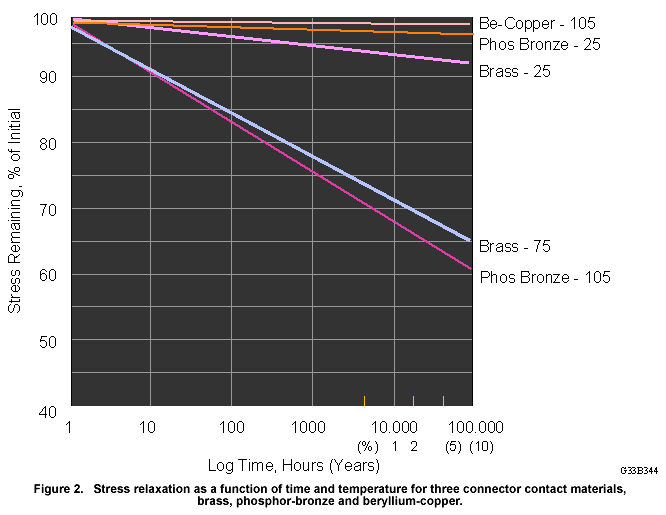
 Equation 2. shows that contact force varies directly with stress, so the stability of contact force over time will vary with the stability of retained stress in the beam over time. Figure 2. illustrates the variation of retained stress for the three example materials as a function of time and temperature. The loss of stress as a function of time and temperature is called stress relaxation. Consider first, the three sets of data at the top of Figure 2. These data show the stress remaining as a function of time at a given temperature. Recalling from Equation 2. that stress correlates directly with contact force, these data also indicate the normalized contact force remaining as a function of temperature. The data for brass and phosphor-bronze are at room temperature, 25°C, while the beryllium-copper data are for temperatures of 105°C. So, at room temperature, a brass contact having a contact force of 100 grams will decrease to approximately 92 grams after 100,000 hours, approximately 11.4 years. Phosphor-bronze will show a contact force decrease to about 96 grams. Practically speaking, at room temperature, brass and phosphor-bronze will show approximately equivalent performance. Note that beryllium-copper at 105°C shows retained normal force higher than either brass or phosphor-bronze at room temperature. The lower set of data shows the superiority of phosphor-bronze to brass at elevated temperature. After 100,000 hours, phosphor-bronze has a retained contact force of 60 grams at 105°C, as compared to 65 grams for brass at 75°C. Thus, brass has a lower operating temperature capability than phosphor-bronze, and both are inferior to beryllium copper in temperature capability. There are other contact materials that show intermediate levels of performance with respect to stress relaxation. The materials described are simply exemplars of materials commonly used in connectors.
This discussion suggests that material selection, dependent on the operating temperature of the connectors, and proper mating practices, are sufficient to ensure the necessary stability of contact force. Another approach to ensuring adequate contact force over life is to begin with an initial contact force that is high enough to tolerate the decrease in contact force due to stress relaxation. The question then becomes, how much contact force can be applied in a connector without introducing other potential sources of problems or degradation? In other words, what performance parameters impact the maximum contact force that can be used in a connector?
One such issue is the impact of contact force on connector mating forces. As contact force increases, the mating force of the connector increases. For higher pin count connectors, mating force may impose an upper limit on the contact force. It must be noted, however, that individual contact mating forces are not the only factor influencing connector mating forces. Contact alignment, both angular and mating centerline tolerances, also contribute. Interference between cavities in the housing may also contribute to mating force. Finally, the use of contact lubricants to reduce friction can produce a significant reduction in mating force.
Another performance characteristic that is highly dependent on contact force, as discussed in the last article, is contact wear. Wear increases with contact force in two ways. Recall Equation 1. from that article, repeated here as Equation 3.:
Equation 3.: V = kF L/H
Where V is the wear volume, the volume of metal removed from the interface during a single wear event, k is the wear coefficient, F is the applied load—in the case of connectors, the contact force—L is the length of motion of the wear event, and H is the hardness of the metals in contact. The focus in this discussion is on k, the wear coefficient. Equation 3. shows that wear increases linearly with contact force for a given value of k. This dependence is overshadowed, however, by the fact that the value of k can increase significantly with contact force, as the wear kinetics transition from burnishing to adhesive wear, as discussed in the last article.
Yet another, and arguably the most important, impact of loss in contact force is the resulting decrease in mechanical stability of the contact interface. The friction force that provides mechanical stability varies directly with the contact force. Thus, depending on the application conditions—thermal and mechanical—an initially stable contact interface may become susceptible to fretting micromotions as the contact force decreases due to stress relaxation. As mentioned at the beginning of this article, fretting micromotions can lead to fretting corrosion in tin-finished systems and an increased susceptibility of corrosion, resulting from fretting wear of the contact finish to the contact spring base metal in noble metal finished systems, as discussed in the previous article on wear as a degradation mechanism.
In summary, concerns for loss in contact force are addressed by material selection to counter the effects of stress relaxation, and proper mating practices to prevent overstressing of contact beams during application of the connectors. These issues are important because of their potential impact on connector susceptibility to micromotions. Micromotions are a major concern as driving forces for connector degradation.
- Nanocrystalline Silver Alloy Contact Finishes in Electronic Applications - April 6, 2015
- Nanocrystalline Silver Contact Platings - March 16, 2015
- Dr. Bob on Gold Flash Contact Finishes (and Max Peel) - September 22, 2014


