Device Connection Integration in the SMT Process
Can the same connector be used in both through-hole reflow and surface-mount device processes? Weidmuller looks at how pin length can make all the difference in meeting the requirements of IPC-A-610 E.

Today’s PCB is a platform for electronic components that creates circuits varying from simple to highly sophisticated. Requirements such as the miniaturization of components, greater functional densities, and lower production costs have resulted in the trend to replace classic through-hole technology (THT) with surface-mount technology (SMT). Today, SMT is the method of choice – it has been widely adopted as the standard production technique for the surface mounting of electronic components.
The soldering technique used in the SMT process is reflow soldering, specifically infrared, convection, or vapor phase soldering. In contrast to the wave soldering process, a solder deposit applied to the PCB is melted. The device connection technology then can be integrated into the SMT process by the through-hole reflow (THR) or the surface-mount device (SMD) processes. These two processes also can be combined.

Process Steps in Surface-Mount Technology
In surface-mount technology (SMT), contacts are established via connections to the housing side or the connection surfaces directly under the housing. Unhoused components can also be used, which are directly mounted onto the PCB with contacts established via wire links or the flip-chip technique.
However, there are still some components, mainly electro-mechanical components like connectors or relays, which are not available in an SMD version; they are, therefore, mounted on the PCB after the actual SMT process itself by applying the classic THT process. An optimal solution for this challenge is a connector developed for the THR process that also makes the wired device connection technique applicable in the SMT process, therefore supporting complete continuity in SMT production.
Through-Hole Reflow
Through-hole reflow refers to processing components, which are inserted through a hole in the PCB and then soldered with other SMT components. It should be noted that the components themselves must be able to withstand the higher temperatures of the SMT process.
THR is a milestone in PCB assembly, defined by the following characteristics: A mechanically stable solder connection is established to the PCB which only requires a soldering process. Manual/wave soldering can be dispensed with and the PCB is automatically populated at low production costs.
Component Requirements for the THR Soldering Process
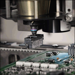
In the case of automatic assembly, mounting is achieved via a vacuum pipette on the placement head; for this reason, the components must have a smooth suction surface. This may be a component surface or a separate pick-and-place pad to which the components are securely fixed from pick-up to set-down. Finally, the component should have a low intrinsic weight.
For automatic sequential assembly or feed of the components, pick-and-place systems are used. Components must be packed in a manner suitable for product-specific handling by robots, whereby a distinction is made between tape-on-reel, tray, and tube.
The soldering process requires high-temperature-resistant materials, an optimized heat supply, and enough space in the soldering area. As the insulating body of the wired component may not come into contact with the solder paste, a sufficiently large stand-off should exist, depending on part size.
Solder Pin Length for the THR Process
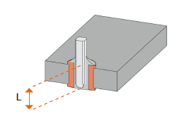
As shown below, the pin length L (more precisely, the pin protrusion on the PCB bottom side facing the component) depends on the chosen soldering process.

Pin lengths of 3.2mm and 3.5mm are suitable for wave soldering. Customized variable intermediate lengths of about 2.1mm or 2.6mm mean that parameters such as paste pressure can be flexibly adjusted.
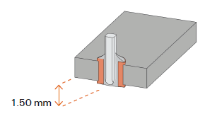
A pin length that is shorter than the PCB thickness has proven ideal for reflow soldering. For PCB thicknesses greater than 1.6mm, a pin length of 1.5mm is recommended for optimum hole fill and optimal paste consumption.
Optimized Pin Length for the SMT Process
For the SMT process, pin lengths of 1.50mm are preferable for several reasons. They meet the requirements of IPC-A-610 E and support double-sided population at PCB thicknesses ≥1.50mm. They also simplify the paste printing process and reduce costs by minimizing the paste volume. In addition, there is the advantage of process acceleration due to optimum temperature absorption and easy degassing of flux in the soldering process. Pin lengths of 1.50mm at a PCB thickness ≥1.50mm are also ideal for vapor phase soldering because no droplets form on the underside of the circuit board.

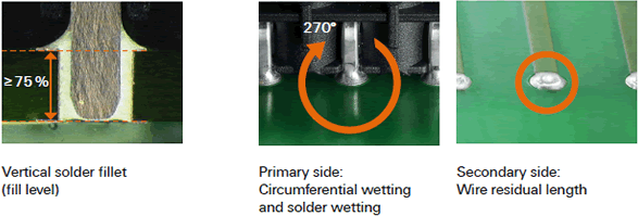
The requirements of IPC-A-610 E realize the need for a pin length of 1.50mm and a PCB thickness of 1.6mm. The vertical solder fillet (fill level) at 1.60mm PCB thickness and with connector pin lengths of 1.50mm is at least 75%, provided that the processing recommendations are complied with. The peripheral wetting of the primary side, that is the underside from the perspective of the components, is not less than 270 degrees. Components with pin lengths of 1.50mm are always shorter than the board thickness of 1.60mm. According to IPC-A-610, the wire end may not be visible at the solder point, as the component should be flush with the board surface (see IPC-A-610 E, 7.3.3, Table 7-3, Note 1).

Surface-Mount Device
In surface-mount technology (SMT), the surface-mounted devices (SMDs) are soldered to the PCB with solder pads. The use of SMD components means that it is possible to dispense with wire connections on the components and mounting holes in the PCB.
SMD offers clear advantages. First, it enables a high packing density and integration of miniaturized components. Second, PCBs can be assembled as desired on one or both sides. Third, quality can significantly be improved by automated population and inspection. Fourth, fully automated handling reduces manufacturing costs. Finally, the small components and the absence of holes and connecting wires decreases the weight of components.
Component Requirements for the SMD Process
Even in the SMD process, a placement head performs the pick-up of components for automatic assembly. The components must have a smooth suction surface, be suitable for the application of pads, and should have a low intrinsic component weight. In the automatic sequential assembly, pick-and-place systems are also used (in this case tape-on-reel and tube). The soldering process also requires highly temperature-resistant materials, an optimized heat supply, and enough space in the soldering area.
Lastly, to ensure reliable soldering quality in the manufacturing process, the contact surfaces of solder pins must be wetted with the solder paste immediately after assembly. This allows the flux contained within the paste to react with the tin coating, resulting in a reliable solder quality. As per IEC 61760-1, coplanarity is between 0.10mm to 0.15mm.
Remember, key considerations in working with THR technology include:
- Optimum pin length: The pin length of 50mm enables space-saving, double-sided population of the PCB.
- Robust insulating body: Moisture-sensitivity level-one THR components can be mounted directly onto the PCB without pre-drying. Durable material ensures dimensional stability and perfect grid.
- High-precision pin connectors: High-precision pin connectors with position tolerance of less than 1mm +/- around the zero position fulfill the standard IEC 61760-3 and remain dimensionally stable.
- Stable position with solder flange pin: Solder flanges make additional fixation with screws redundant.
- Stable solder connection
- Reliable processing
- Efficient assembly: High component precision and low weight support the assembly process. In addition, a high number of components per roll increases efficiency.
To read this whitepaper from Weidmuller in its entirety, including the design steps for both the through-hole process and the SMD process, click here.


