Great Connector Inventions: Connector “Chicklets” Revolutionize Backplanes
Chicklets revolutionized automation by increasing the overall speed and efficiency of designing in backplane connectors.
 The Germans are renowned for developing and enforcing mechanical standards that are used worldwide. German companies developed the DIN 41612 connector family and the Eurocard chassis standards, which remain the basis for many other standards, such as VME architectures used in telecom, industrial, medical, and computing systems. The VME architecture was an interesting mix of imperial dimensions (19-inch racks and N x 0.100″ card pitch but with metric daughtercard dimensions of 100mm x 160mm).
Siemens EC, led by Karl Zell, had a dream of a generation of standards that would be pure metric. The team called this “hard metric,” since it would have no inch-based dimensions. The concept was to have a totally metric 3D space for rooms, racks, shelves, cards, connectors, and even shipping containers. From a connector perspective, this concept was to specify a consistent 12.5mm dimension from the leading edge of the daughtercard to the backplane (consistent with the previous dimension used for DIN connectors); connector modules would be N x 25mm long. This dimension was called a Systems Unit or SU for short. So standard cards would use nine SU connectors, for example, for the metric analog to the Eurocard. Siemens developed “SIPAC,” a family of five-row 2.5mm-pitch connectors to fit this pure metric architecture with 2U, 4U, and 9U connector blocks standard.
AMP, working with Siemens EC, endorsed the metric packaging idea and the 25mm SU but liked the higher density offered by a 2mm pitch, so it developed the Z-Pack 2mm HM connector (HM for hard metric; now available from TE Connectivity) with modules 25mm or 50mm long. By using the same SU as “SIPAC,” 2.0mm- and 2.5mm-pitch connectors could be mixed on the same board, in the same metric equipment practice. To reach the highest possible density, combined with accurate alignment and 60 keying possibilities, AMP introduced the idea of having an optional guidance module in the center of the 2SU 50mm connector.
The AMP designers embarked on a dramatically different connector design using insert-molded lead-frame technology. This was a very important decision with long-term implications. The Berg Metral connector had a metric 2mm pitch between columns and rows at the mating interface, but the space between rows at the daughtercard interface was 1.5mm, and the dimension between the leading edge of the daughtercard and the backplane was 10mm. The choice of a 12.5mm pitch between the leading edge of the daughtercard and the backplane enabled the 2mm HM connectors to immediately fit into the Eurocard equipment practice at the time without changing existing board sizes, an attractive feature to the VME standards organization.
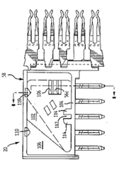
 The breakthrough innovation with this connector family is the use of “chicklets.” Columns of contacts were stamped as a lead frame, then overmolded reel-to-reel. You can imagine that stamping five contacts at a time is more efficient than stamping contacts one by one. The dies were more sophisticated and the contact design needed to be material-efficient to enable stamping contacts on pitch. This approach offered several benefits to the connector manufacturer:
- Lead frames on reels were easy to handle through stamping, plating, overmolding of the plastic, and subsequent stitching of chicklets into a connector front housing.
- This level of automation raised the bar for quality and consistency.
- Multi-cavity overmolds were quickly developed, further increasing productivity and reducing cost.
- Inspection processes were also more efficient.
- By stamping all the right-angle bends in the die, the assembly process was vastly simplified. Simple stitching machines excise the chicklet from the carrier and insert five contacts with each stroke with no bending.
- The overmolded pin tails were very accurately positioned, overcoming a significant issue for high-pin-count connectors.
- The tails were also very short and robustly fixed in the housing, facilitating the use of compliant press-fit tails.
- The flat surface on the top of the chicklet also allowed the use of low-cost “flat-rock” insertion tooling.
- The lead-frame design combined with overmolding also improved the impedance consistency through the connector.
It is easy to see that introducing overmolded wafers to backplane connectors was a breakthrough invention; the creativity and vision of Herman Gilissen and Jan Broeksteeg changed the backplane connector industry forever, with the help of the process-development teams that were able to create the sophisticated stamping dies, overmolding processes, and assembly equipment that made 2mm-pitch connectors both better and more cost-effective.
PICMG (PCI Computer Manufacturing Group) was formed to develop standards around the new 2mm HM connectors to ensure that cards from many manufacturers could be used interchangeably to build a variety of systems. This working group created a new standard, CPCI or CompactPCI, that is very broadly used across many industries, including telecom, computer, industrial, medical, and the military. This standard specifies the Eurocard form factor, but for the 2mm HM connectors. AMP (in collaboration with Siemens EC) also made this an open standard, which allowed many manufacturers to tool these connectors. TE Connectivity, ERNI, HARTING, Molex, 3M, Foxconn, AVX, JAE, and several other producers now make 2mm HM connectors.
The engineers quickly realized that this connector performance could be enhanced by adding shielding. Plates were added above and below the connector housing that limited EMI (electromagnetic interference), alleviating systems designers’ concerns by eliminating one more problem in system development. These L-shaped shielding plates press-fitted into the daughtercard and mated with ground pins in the mating headers, effectively adding an additional two rows to the connectors dedicated to ground.

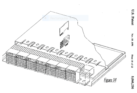
Patent Illustration showing 2mm HM with shields between chicklets
External shields do little to control crosstalk inside the connector itself and are of no value for controlling connector impedance. To address these issues, they re-used a feature applied successfully in AMP’s 0.100″ Strip Line cable connectors, inserting ground planes between wafers. These shield lead frames have a receptacle contact that mates with the bottom row of pins. This ground structure created an environment that both controlled impedance and dramatically reduced crosstalk between adjacent wafers. This was another industry-changing invention from Den Bosch, The Netherlands, that made the decade of the 1990s the golden age of backplane connector innovation.
It is an interesting footnote that the described shields-between-wafers concept at AMP never reached production. The most common 2mm HM configuration evolved by designating the center row of pins as grounds, enabling two differential pairs in each wafer with the +2 ground shields outboard.
Learn more about other inventions in connectivity:


