Choosing the Right RF Cable Assembly
Choosing the Right RF Cable Assembly
The following is an excerpt from a white paper by Dave McReynolds of RF Industries. McReynolds thoroughly examines the many parameters to consider when choosing an RF cable assembly, with special regard for the applications for which it will be used. There is much more included in the original white paper, so to read the document in its entirety on the RF Cable Assembly site, click here.
Coaxial cable assemblies are found in almost every electronic system. They have a simple job: To serve as a signal path to transfer signals from one location to another. But they must do that job without fail and with little or no change to the signals, whether they are high-frequency analog signals or high-speed digital signals. Because coaxial cable assemblies are so vital to such a wide range of systems, from rugged ground-based electronic systems to satellites orbiting in space, the selection process for those cables should not be treated lightly. Choosing the right coaxial cable assembly is not a trivial task, but it is one that can be made somewhat easier by knowing what to look for in a high-frequency or high-speed coaxial cable assembly.
Coaxial cables provide the means for transverse-electromagnetic (TEM) modes of transmission. The name refers to their construction, which typically consists of a bare copper round wire inner conductor, solid or stranded, surrounded by a tubular dielectric insulator, which is surrounded by a tubular outer conductor or shield that is surrounded by some form of protective outer layer, usually plastic. The coaxial cable is the brainchild of British mathematician Oliver Heaviside, who patented the concept in the late 19th century. He had been studying skin effects in telegraph transmission lines, determining that wrapping some form of insulator around the transmission line would improve its performance. The first commercial use of a coaxial cable in the United States was a 220-mile-long run of coaxial cable between Stevens Point, Wisconsin, to Minneapolis, nominally for telephone lines.
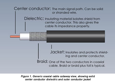
For effective use with high-frequency analog signals or high-speed digital signals, the dimensions of the different parts of a coaxial cable must be precisely controlled to achieve constant conductor spacing. The coaxial construction (Figure 1) confines the electric and magnetic fields of conducted signals within the dielectric insulator while preventing electric and magnetic fields outside the outer shield layer from interfering with conducted signals. A coaxial cable becomes an assembly when it is terminated in a customer’s choice of coaxial connectors. Coaxial cable assemblies are commonly used in cable-television (CATV) installations, for high-frequency RF/microwave connections, in precision test and measurement equipment and systems, and for transferring high-speed digital signals in computer networks.
Coaxial cable assemblies typically have characteristic impedances of either 50Ω or 75Ω, and these impedances are not by chance. The two values trace back to pioneering work performed at Bell Laboratories in 1929. Those early experiments sought optimal characteristic impedances for transferring high power levels as well as for achieving minimal signal loss. Ideally, the same characteristic cable impedance would support both conditions, but that is not the case. A characteristic impedance of 30Ω was found to be optimal for transferring signals at high power levels, while 77Ω was found to be well suited for minimizing the loss of high-frequency, high-speed signals. The Bell researchers also found that 60Ω was the best characteristic impedance for high-voltage signals. The 50Ω impedance was chosen as a practical compromise between the power-handling capability at 30Ω and the minimal attenuation at 77Ω, while 75Ω was selected as a good match for a center-fed dipole antenna in free space for use in radio systems.
When specifying a coaxial cable assembly, it helps to understand the electrical and mechanical parameters of different cable types and how to compare them. RF/microwave coaxial cables can be grouped into three categories: Semi-rigid and conformable (or hand-formable) cables, flexible cables, and corrugated cables. Each is constructed differently, with different mechanical characteristics and different levels of electrical performance.
Semi-rigid cables, so called because they offer more flexibility than rigid cables, are known for their excellent electrical performance but limited formability. Because of their lack of flexibility, they usually require the use of three-dimensional (3D) engineering drawings for proper integration into most electronic systems. But choosing a coaxial cable assembly involves trade-offs, and for the sacrifice in flexibility, semi-rigid cable assemblies provide superior electrical performance compared to the other two coaxial cable types, and offer uniform impedance, low insertion loss over wide frequency ranges, and excellent shielding effectiveness (SE, a parameter that characterizes both cable leakage and susceptibility to outside electromagnetic sources).
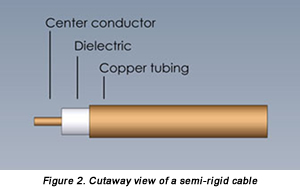
Semi-rigid cables are typically constructed with a solid center conductor surrounded by a dielectric insulating material, covered by a solid tubular outer conductor (Figure 2). The center conductor is usually silver-plated copper, which is nonmagnetic and supports low-loss performance. The outer conductor is typically formed of aluminum or copper, which is bare or plated with tin. In contrast to rigid cables, semi-rigid cables are typically characterized by the cable outer diameter: 0.034, 0.047, 0.086, or 0.141 inches. Small-diameter semi-rigid cables can support operating frequencies as high as 110 GHz, but with maximum power-handling capabilities of a few hundred watts and typically much less. Rigid cables, in comparison, have outer diameters ranging from 0.875 to 8.1875 inches. They offer power-handling capabilities of kilowatts at lower frequencies, typically up to 800 MHz for applications such as commercial radio and television broadcast transmitters.
The solid outer conductor provides excellent SE performance in semi-rigid cables, with some sacrifice in flexibility. The high shielding values enable semi-rigid cables to achieve excellent electrical performance even in environments with high-level signals near transmit antennas. Using different configurations for the outer conductor, manufacturers of coaxial cables have improved the flexibility of their cables while still achieving high SE levels. The outer conductor or braid layers have been designed with flat metal wraps, round metal wraps, strips of metal with and without coatings, and in single-layer, double-layer, and triple-layer configurations to provide a wide range of SE values with low insertion loss while also achieving some measure of flexibility in the cable.
Conformable cables offer a great deal of the electrical performance of semi-rigid cable assemblies, but with somewhat more flexibility to ease difficult installations and connections. Conformable cables are not designed for repeated flexure, but can be bent (within the limits of their minimum bend radius) to a required shape and will retain that shape once bent. For good electrical performance, conformable cables are constructed with silver-plated copper conductors or silver-plated, copper-covered steel conductors and a copper-tin composite shield design that provides high SE.
Flexible cables sacrifice some of the electrical performance of semi-rigid cables, but their greater flexibility simplifies installations in systems. In place of the solid conductor of a semi-rigid cable, a flexible cable often employs a stranded center conductor. Instead of the semi-rigid cable’s solid outer conductor, a flexible cable uses a polyurethane or fluorinated ethylene propylene (FEP) outer jacket. A number of different dielectric insulator materials may be used in a flexible cable assembly, including polyethylene, solid polytetrafluroethylene (PTFE), and high-density polyethylene foam. The foam’s air content lowers the dielectric constant of the insulator material while helping reduce cable attenuation.
For example, a flexible coaxial cable might use an outer conductor formed of silver-plated copper wires braided over the insulator, silver-plated copper strips in a basket weave, or silver-plated copper wires set parallel to each other and in a long spiral configuration. The center conductor may be solid copper, to minimize cable loss, or stranded, for applications that may require repeated flexing of the cable, albeit with higher loss than cables with a solid center conductor.
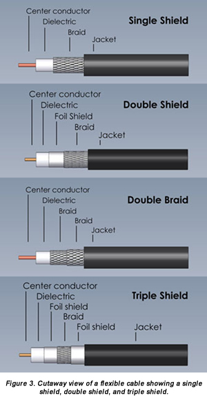
The braid layers in flexible coaxial cables allow very good flexibility when combined with a center conductor and outer jacket that also support flexure. Because a wire braid has air gaps between strands in the braid pattern, shielding is not continuous. The size of the air gaps can increase with flexure, compromising SE at those spots in a single braided cable. To ensure high SE, additional braid layers, including helical and/or ribbon braids, may be added to form a double-shielded or triple-shielded cable with more continuous shielding coverage (Figure 3). The tradeoff when choosing a thicker braid with two or three layers is additional stiffness and loss of flexibility in the cable. Cable manufacturers use percentage of shielding coverage in their specifications to indicate the effectiveness of shielding in a cable assembly.
Braids for coaxial cables are available in a range of materials and types, with each representing trade-offs. A braid layer formed of round wire provides good flexibility and has the lowest material cost but, as noted earlier, can suffer performance degradation with flexing. More sophisticated braid materials represent increased material costs, but more consistent performance over time. For example, a shield formed of flat metal ribbon can deliver low cable attenuation with high SE performance, while maintaining consistent electrical performance over time. A helical flat braid supports good flexibility, while also enabling excellent phase stability with cable flexure and high SE levels. A wrapped or folded foil braid can also provide high electrical performance, with good mechanical strength but with some loss of flexibility compared to other braid configurations.
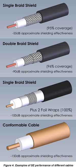
The number of braids will impact both flexibility and SE. Depending on the shield material, like copper wire braid, and whether it is silver-coated, a coaxial cable with a single braid layer can deliver SE of 40dB or higher with very high flexibility. With each added braid layer, the cable’s flexibility decreases as the SE increases. A double braid layer formed of two round-wire braids can typically deliver better than 60dB shielding. But if a foil shielding or woven flat braid is used for one of those braid layers, the SE can be increased to 90dB. Double-shielded cables using a foil shield under a tin-filled composite layer can achieve better than 100dB SE while still achieving reasonable flexibility. High SE values are possible with triple-shielded cables that combine round wire and woven flat braid layers, although with some sacrifice in flexibility (Figure 4).
Coaxial cable assemblies are defined by not only the type of cable but by the coaxial connectors on either end of the assembly. For the best application match, the different cable types can be compared by means of standard electrical and mechanical parameters, but such comparisons should always compare similar lengths of cable with similar coaxial connectors at both ends of the cable assemblies being compared.
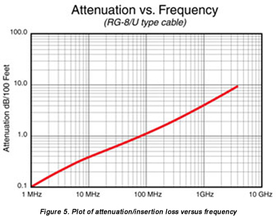
In terms of amplitude and phase characteristics, a coaxial cable assembly should be electrically invisible within a system, providing a signal path between two points in the system with minimal effects on the transferred signals. In the real world, however, cable assemblies can make alterations to the signals they carry, although a proper choice of cable assembly can help minimize these effects. Cable assemblies are typically characterized by a number of different electrical and mechanical parameters (Figure 5): Cutoff frequencies; attenuation or insertion loss (in dB/ft. or dB/m); return loss or voltage standing wave ratio (VSWR); capacitance (pF/ft.); velocity of propagation (VP, in %); power-handling capability (in W); and even weight (lbs/ft. or lbs/m). These different parameters can provide useful yardsticks for comparing cable assemblies from different suppliers.
By Dave McReynolds, Director of Engineering, RF Industries
- Facts & Figures: Semiconductor Market Grew to a Record $336 Billion - March 2, 2015
- TLC and Metz Ethernet Cat 6A Patch Cords in Seven Vibrant Colors - January 27, 2014
- Cables Unlimited LC-LC Duplex Ruggedized Fiber Jumpers - January 27, 2014