Inter-Vehicle Jumper Systems for Rail Transport
Today’s inter-vehicle jumper systems must withstand a diverse array of electrical, mechanical, and climatic conditions.
 Today’s inter-vehicle jumper systems must be capable of withstanding a diverse array of conditions, so the system’s design must consider the flow of current and the resulting heating, vibration, bending, and torsion, as well as ambient temperature, ballast strikes, weathering, oils and fluids, and various types of cleaning agents, to ensure long-term service life. The requirements for reliable electrical connectivity from vehicle to vehicle are subject to the conflicting priorities of cost and benefit (service life). The more energy that is required, the denser the signal transmission and data traffic. Each of these factors adds to the complexity of the cable construction, which influences costs. Inter-vehicle jumper systems must satisfy the technical requirements of customers as well as the demands of the market, so there must be a positive cost/benefit ratio. To make this possible, a number of considerations must be kept in mind when developing and designing electrical inter-vehicle jumper systems.
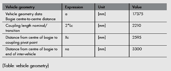
Basics: Vehicle Geometry
Designing a reliable system requires precise specifications. The vehicle geometry data is a particularly important factor.
Load Test: Relative Movement Between the Vehicles
Electrical inter-vehicle jumper systems are installed between two mechanically coupled vehicles and may contain power, signal, communication, and data cables. It is essential to know exactly how the two vehicles move so that the system can be designed in such a way that this movement does not exert too much strain on the transition. Kinematic aspects, together with the vehicle geometry, form the basis of the system design.
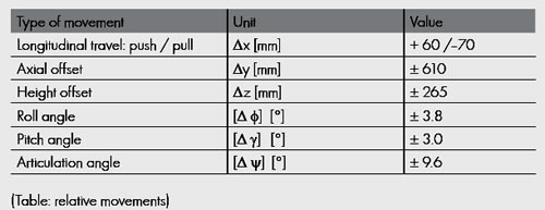
Push and Pull: Longitudinal Travel
The extent to which the coupling compresses and decompresses in the coupling axis when accelerating and braking is referred to as longitudinal travel.
Lateral Deflection: Axial Offset
When a train crosses a set of points, for example, two coupled wagons will experience an axial offset with respect to one another. This relative deflection is known as the axial offset. Of significance in its calculation is the bisector of the articulation angle of the two vehicles, which is located exactly midway between the front walls of the two vehicles and relates to their longitudinal axis.
Higher and Lower: Height Offset
If the vehicles move vertically in relation to each other, this is referred to as the height offset, and it takes the pitch angle into account. The significance of its calculation is the bisector of the pitch angle of the two vehicles, which is located exactly midway between the front walls of the two vehicles.
Back and Forth: Roll Angle
If a vehicle starts to roll, the rotation around its own axis is referred to as the roll angle. This is expressed as a relative angle between two vehicles.
Up and Down: Pitch Angle
“Pitch” is understood to be the vertical movement of a vehicle. It is caused by the influence of varying forces at a particular level that lie between the fronts of the vehicles. The pitch angle thus describes the relative vertical angle between two vehicles.
Left and Right: Articulation Angle
When a train travels around a curve, the relative horizontal angle between two vehicles changes. This change is known as the articulation angle.
A decisive factor in the design of an inter-vehicle jumper system is the totality of all six relative movements and their maximum amplitudes, which are summarized in the table below.
The vehicle geometry data and the relative movements directly affect the cable bending radius and the torsion, which together define the limits of the system. The bending radius, in turn, depends on the cable construction and the choice of material used for the cable jacket. HUBER+SUHNER RADOX materials and cables are designed specifically to meet these requirements.
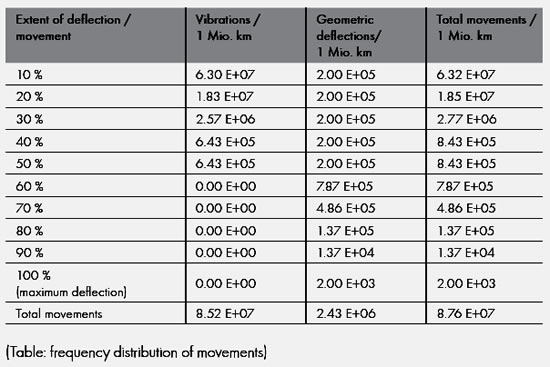
The Frequency Distribution of the Movements
Of course, not every movement in the day-to-day operation of a train results in a maximum deflection. Different curve radii also generate different degrees of cable bending. The greater understanding we have of the loads that occur, the more accurately we can predict the service life of an inter-vehicle jumper system cable.
If one knows the route profile of a train, then the frequency distribution of the movements can be calculated. This distribution then becomes another variable in the design of the cable. The movements listed below are half cycles: They start from their normal position and go to their respective maximums and back again.
Effect of Ambient Temperature
An ambient temperature in the range of -25°C to +90°C poses no particular problems for HUBER+SUHNER inter-vehicle jumper systems during normal operations. At lower temperatures, down to -50°C, additional attention must be paid to the design of the cable. The prescribed standard tests, such as the cold winding test and impact test, are no longer adequate in such cases, as they do not satisfactorily reflect true operating conditions. HUBER+SUHNER therefore carries out in-depth movement tests in climatic chambers down to -50°C.
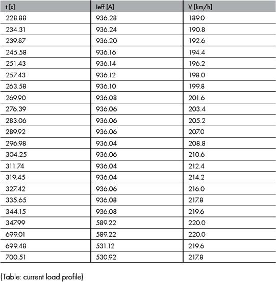
Determining the Permitted Operating Temperature
In order to determine the permitted operating temperature of an inter-vehicle jumper system cable, it is not sufficient to consider the ambient temperature alone; the heat generated by the flowing currents must also be taken into account. This is done using current load profiles. Once the current load is known, an appropriate cable cross-section can be determined that will limit the maximum jacket operating temperature from being reached. Although the design of current load profiles is highly complex, it is the calculation that most closely approximates operational practice: [ i = f(t); W = i2*dt ].
The following table provides a good starting point for a current load profile. It shows the current flow as a function of time and the speed of the vehicle.
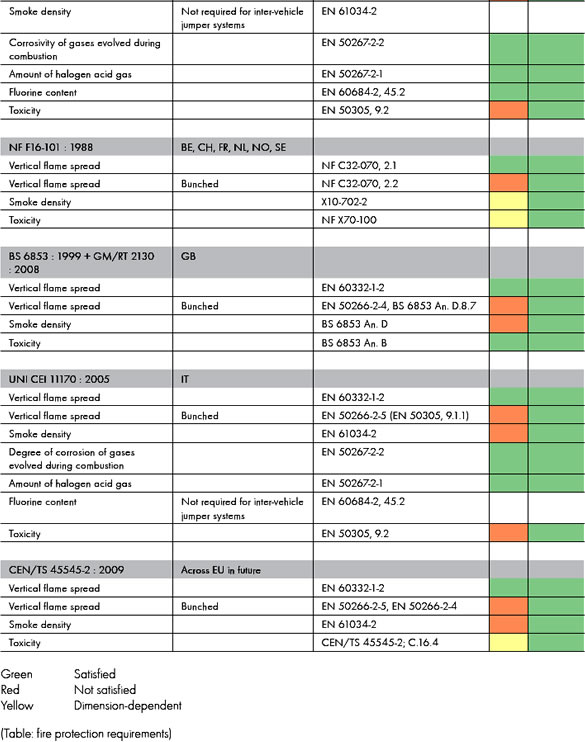
Fire Safety Requirements
Customer specifications frequently quote several fire protection standards that require full compliance. This demands a high degree of flexibility in the material used in the cable jacket and a careful choice of material. The cross-linked RADOX EM104-J jacket material from HUBER+SUHNER fulfills the majority of today’s most commonly used fire safety requirements and offers significant advantages compared with non-cross-linked TPU/polyurethane materials.
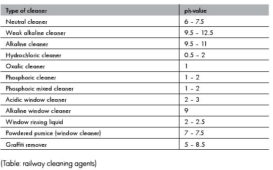
Resistance to Cleaning Agents
Dust, ozone, sulphur dioxide, salt and salt spray, coolants, anti-freeze, hydraulic fluids, and lubricants are all airborne agents that can occur on the railways. Inter-vehicle jumper systems must demonstrate resistance to most commonly used railway cleaning agents. This list shows the cleaners and their pH values.
Powerful Impact: Ballast Strike
Ballast strikes the underside of the vehicle at the approximate speed the train is traveling. This can result in serious impairment of the system, particularly in the case of low-hung inter-vehicle jumper systems. The risk is particularly pronounced in high-speed vehicle movements.
The ballast strike phenomenon can be caused by:
- Aerodynamic loads, in particular the increased longitudinal flows underneath the train
- Falling ice, which occurs when accumulated ice works loose at high speeds and falls on the track bed
- High ballast levels
- Monobloc concrete sleepers
- Size of ballast
A distinction is made among the following degrees of damage:
- Light, sporadic ballast strike by chips of ballast weighing up to 70g
- Sporadic strikes by chips weighing up to 150g
- Massive ballast strike, caused by falling ice, involving chips of ballast weighing up to 200g
The cable insulation may be damaged, depending on the weight and speed of the ballast. Attention must be paid to any nicks in the sleeve insulation. If any nicks or cuts are found in the cable, it must be replaced as a matter of urgency in order to avoid the risk of further damage, which will cause premature failure on the inter-vehicle jumper system and continued running service of the vehicle. Protection against the effects of ballast strike can only be achieved through design measures, or the addition of wind deflectors and protective plates.
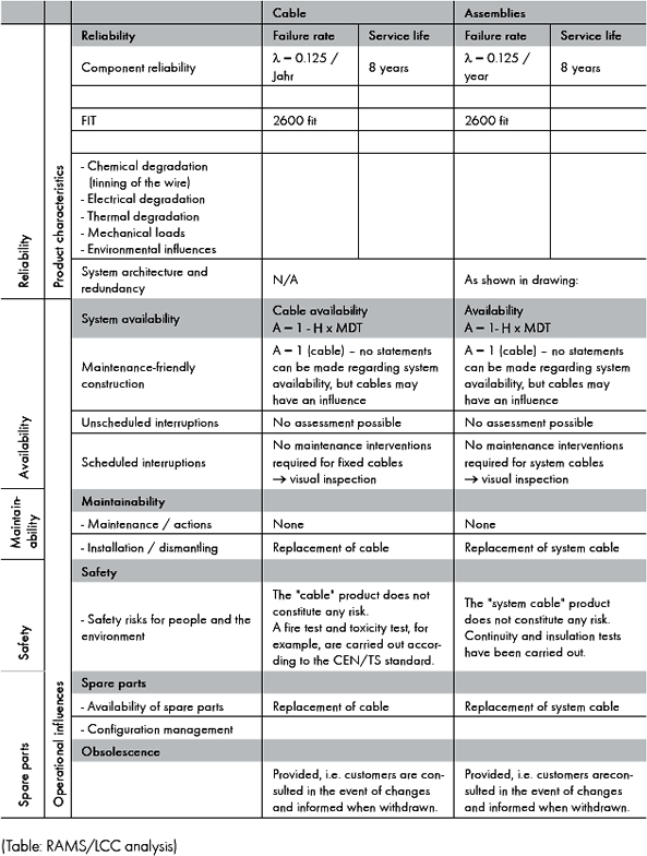
Service Life and Costs: The RAMS and LCC Analysis
Vehicle operators demand long service life from products with the highest levels of safety, functionality, and economy. This means:
- Total reliability
- Simple maintenance
- Efficient fault detection
Movement clearance, cable design, and environmental influences play an important role in determining the service life of inter-vehicle jumper systems (RAMS analysis). The key words are reliability, availability, maintainability, and safety, or RAMS. Below is an example.
Greater Protection: The Cable Design
Suspension and guidance are the main factors determining the service life, and hence the cost efficiency, of inter-vehicle jumper system cables. The stranding of the individual components is user-specific and has a positive effect on pliability, flexibility, and stability. The torsional load on the cable elements is reduced, and special design features guarantee excellent operational stability. The compact design offers the individual cable elements greater protection against vibration and acceleration than the looser design commonly found in corrugated tubes.
Less Load: The Design of the Connections
HUBER+SUHNER encases the cables in an anti-kink sleeve, which effectively joins them permanently to the cable jacket. This construction ensures that torsional forces are transferred to the cable penetration (plug and sleeve) and that the cable elements are not exposed to any clamping forces. It also prevents the cable from kinking when it is bent.
The operational benefits of the anti-kink sleeve are obvious: As the cable elements are “supported” by the cable jacket, the sleeve, and the screw fastening, they are not exposed to any load and cable elements do not get trapped clamping points by screw fastenings.
The UNI-DICHT Strain Relief System
The deliberate clamping area gradation of the UNI-DICHT system provides an optimal transmission of clamping forces to the individual components involved. As the pressure is distributed over a wide area, there is no chance of any damage. Sealing to IP68 and cable relief is also guaranteed. The UNI-DICHT inserts are also fitted with a membrane that provides sealing to IP54, even if the fastening is not appropriately tightened.
Shorter Service Life: The Standard Commercial Clamping System
Compared with the HUBER+SUHNER UNI-DICHT system, clamped joints and other systems with cable relief have obvious drawbacks. For example, these types of construction are not accompanied by a manufacturer’s guarantee. The cable elements are self-supporting due to the clamping effect of the screw fastening, so their service life is reduced dramatically.
In addition, the torsion permanently damages the clamp between seal and jacket, which can, among other things, cause condensation to form. Condensation provides a breeding ground for bacteria, which may attack the cable’s insulation material, causing degradation. Furthermore, ice is likely to form when the temperature drops below zero, and the torsion in the seal will mean that the required protection class will only be provided for a short while. The cable may kink if it is bent in the vicinity of the clamp, and the length difference in the unstranded elements, which have simply been twisted, makes it significantly more sensitive. If vibration in the case of clamped joints and other systems with cable relief is not considered, they can also have negative repercussions.
Cable Relief Using an Anti-Kink Sleeve
Cable relief for the cable jacket on HUBER+SUHNER’s system cables is provided by the anti-kink sleeve on the screw fastening. This construction produces an even, parabolic transition from the moving cable to the rigid screw fastening and increases the service life markedly — 10 to 20 times higher than for systems without the sleeve. The diameter and length of the sleeves are adapted to suit the installation requirements and the complete bushing – cable, sleeve, and screw fastening – is torsion-proof, dust-proof, and waterproof.
HUBER+SUHNER inter-vehicle jumper system cables with anti-kink sleeves benefit from clear and reproducible installation conditions without imposing any radial constraints on the internal cable structure. Their small diameter also means they can be used in situations where space is at a premium. Another benefit of screw fastenings is that they enable the service life to be calculated in advance: approximations can be made by carrying out dynamic long-term tests.
Even though the corrugated tube solution and screw fastenings of various manufacturers have the advantage of easy-to-use assemblies, the undefined pressure of the screw fastenings on the cable dramatically reduces service life – partly as a result of the ensuing sealing problems. Because only part of the diameter of the corrugated tube is used, the dimensions are much larger, so it takes up more space with limited bending radii.
Retrofitting of additional cores, however, is only possible by modifying the cable (assuming the layout inside the cable permits),whereas this can be done without any difficulty in the case of corrugated tube versions, although the capacity of the pipe will be a limiting factor.
[hr]
 Urs Meissner is product marketing manager, cable systems for railways, at HUBER+SUHNER in Pfäffikon, Switzerland. Many thanks to Rudolf Benninger, cable design engineer at HUBER+SUHNER, for his valuable technical input for this paper.