Materials Impact Microwave Cable Performance
In today’s microwave cable assemblies, it is essential to identify the electrical, mechanical, environmental, and application-specific constraints that affect overall performance, which are impacted by the materials used for cable dielectric and jacketing.
 Ensuring high-quality signal stability of cables for microwave applications means evaluating the dielectric and jacket materials for attributes that account for the harsh elements of the application. The dielectric materials used in signaling cables affect the signal integrity as well as robustness of the cable. The material used in an outer jacket affects maximum voltage and resistance to abrasion. Jacket materials must survive most of the external factors (e.g., temperature, friction, liquids, and gases) to protect the conductors inside the cable. The list of possible materials used in cable dielectric and jacketing is very long, and many of these have been developed for specific applications. Because each material has unique properties, some are more appropriate than others for use in microwave cables engineered for challenging environments.
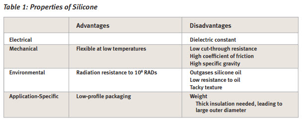
Silicone
Silicone is primarily used as a cable jacket and is very flexible, even at low temperatures (Table 1). However, it cuts easily, and its sticky surface results in a high coefficient of friction, so it is not good for cleanroom environments. Silicone’s tensile strength and tear resistance are low, therefore requiring it to be thicker as compared to other jacket materials. Some surface treatments are available to reduce the coefficient of friction, but these tend to wear off over time. Silicone has very good radiation resistance, but the grades of silicone used for cable jackets are known to outgas silicone oil in vacuum applications such as a thermal vacuum chamber. If weight is an issue, silicone is not the optimal choice. If flexibility is important and weight is not a factor, silicone is a good choice. However, it is more labor-intensive to gain access to the conductors, which results in higher costs for termination.
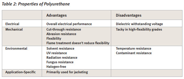
Polyurethane
Polyurethane is a good jacket material, but it is not used as a dielectric material because its dielectric withstanding voltage is low when compared to other materials (Table 2). Halogen-free grades are available. Mechanically, polyurethane is flexible, and it is very resistant to cut-through and abrasion. Treatment for flame resistance does not reduce its flexibility; however, the more flexible grades tend to be sticky or tacky, which results in a higher coefficient of friction. Environmentally, polyurethane is resistant to solvents, UV rays, radiation, and fungus. Polyurethane does not have a very broad temperature range; it becomes brittle around -40°C, and its upper temperature limit is around 100°C. Also, polyurethane cannot survive the chemicals used for cleaning.
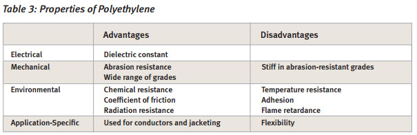
Polyethylene
Polyethylene is most appropriate as a dielectric for conductors because polyethylene jackets tend to be stiff, which affects the flexibility of the cable (Table 3). Polyethylene has good dielectric constant properties when used in conjunction with foam. Mechanically, high-molecular-weight polyethylene is abrasion-resistant and low-friction, but it is also stiff when compared to other materials. Like polyurethane, polyethylene’s temperature range is rather limited, and it is difficult to bond chemical boots to polyethylene cable jackets. Overall the mechanical properties of polyethylene are reduced by flame-retardant treatments.
Fluoropolymers
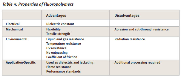
Fluoropolymers such as fluorinated ethylene propylene (FEP), perfluoroalkoxy (PFA), and polytetrafl uoroethylene (PTFE) are excellent jacket materials, particularly in applications when the cost of system failure is high (Table 4).
The dielectric withstanding voltage of fluoropolymers is among the highest of any dielectric material. Fluoropolymers can withstand extreme temperatures, but each material has its own range: FEP can handle temperatures ranging from -250°C to +150°C, while PFA ranges from -250°C to +200°C. PTFE is suitable for temperatures from cryogenic to +260°C without losing flexibility.
Fluoropolymers can also withstand exposure to chemicals, acids, and aggressive solvents, and they are naturally non-flammable. PTFE and its co-polymers also have the benefit of low outgassing, which is critical for ultra-high vacuum (UHV) environments. Most fluoropolymers are flexible, but like temperature resistance, flexibility varies depending on the specific material. PFA is the stiffest, followed by FEP and PTFE, and engineered PTFE is the most flexible. Anything that is added to a cable’s dielectric, jacket, conductors, or shield wires will outgas in a vacuum. When materials outgas, particulate matter condenses on the cooler surfaces typically found in the application area. In a satellite, optics can become fogged by silicone oil or other processing lubricants that outgas from a cable. PTFE is chemically inert and does not contain any process additives, oils, lubricants, or plasticizers, which makes it the best material for vacuum environments.
Engineered Fluoropolymers
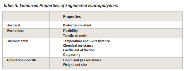
One of the few negatives of fluoropolymers is that they are not very resistant to abrasion and cut-through. Certain fluoropolymers can be engineered to enhance their physical, chemical, and electromagnetic attributes, which improves a cable’s ability to withstand the specific challenges of a microwave application. Ethylene tetrafluoroethylene (ETFE) can be irradiated to improve its mechanical properties and chemical resistance; however, irradiation increases stiffness, so there is a significant decrease in flexibility. PTFE is naturally thermal-resistant and chemically inert, so its temperature and chemical properties are not altered when engineered to enhance electrical or mechanical attributes.
Specialized technologies have been developed to engineer PTFE so that it can withstand a wide variety of environmental and mechanical challenges (Table 5). The dielectric materials used to insulate conductors can significantly affect insertion loss, cable size, and flexibility. The lower the dielectric loss, the less insertion loss the cable exhibits. Typical fluoropolymers have a dielectric loss of 2.1. To reduce cable size, PTFE can be engineered to have a dielectric constant of 1.3. At the same time, its dielectric withstanding voltage can be increased by a factor of 2.5 while achieving a very low loss tangent of 0.00015 at 10GHz compared to PTFE’s standard construction. With these attributes, a conductor insulated with a 1/2000th-inch (50-micron) layer of engineered PTFE can be rated for use at 1,000 volts. Another version of engineered PTFE can be made semiconductive and used to increase the effectiveness of a cable’s shield. For issues of abrasion or cut-through resistance, PTFE has been engineered to attain a tensile strength that is 50 times greater than standard PTFE and to withstand temperatures from cryogenic to +300°C.
The environments in which microwave cable assemblies are being used today are becoming more challenging, with exposure to such conditions as extreme temperatures, chemicals, abrasion, and flexing. Additional challenges include the need for smaller, lighter packaging for cable systems that lasts longer and cost less. To ensure signal integrity and product reliability, it is essential to identify the electrical, mechanical, environmental, and application-specific constraints that can affect the cable’s overall performance. These variables have a direct impact on the materials used for cable dielectric and jacketing as well as the construction of the cable.
This article was contributed by W.L. Gore & Associates. To read the white paper in its entirety, click here.