Selecting the Ideal Spring-Loaded Connector for Portable Applications
Our portable devices would not be possible without proven connector technologies that facilitate miniaturization and connectivity.
By Stephen Capitelli, Manager of Product Engineering, Mill-Max Mfg. Corp.
Today’s electronics designers are challenged to find the right balance between reliability, suitability, and cost as they specify the components needed to create successful and competitive products. The first step in the search process is to fully understand the application and the requirements that it will put upon the connectors involved.
In some applications, the connector is mated once during production. In others the connector is an integral part of the device, such as in a docking station or a charger. Each of these applications requires a different solution. A correctly applied connector will function better — and last longer — than one that is not well suited for the application. Gathering and using this knowledge is another connector-related challenge for today’s designers.
There are several methods for creating the pins used in connectors. The most flexible is precision machining. This not only provides high levels of quality and reliability, but also offers significant flexibility in terms of design and materials, allowing designers to specify connectors to suit their exact needs. The resulting high-precision pins have a cylindrical geometry and are sometimes called turned pins.
Typical turned pin sizes range from 0.008” (0.2032mm) to 0.250” (6.35mm). High-speed turning can consistently produce precision-machined pins to tight tolerances of ±0.0005” (0.0127mm) on all critical features that are essential to the functionality of the pin as a connector. Not only is this process highly accurate, but its repeatability is excellent — whether a thousand or a million pins are being manufactured.
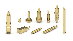
The main components in the spring-loaded connectors (SLCs) are the spring-loaded pins, sometimes called spring-loaded contacts, spring probes, or pogo pins. These provide a highly reliable, precision-made interconnect solution ideal for a wide variety of demanding applications. Each spring-loaded pin is precision-machined to ensure a high quality, low resistance, and compliant connector, which gives it an edge over other technologies.

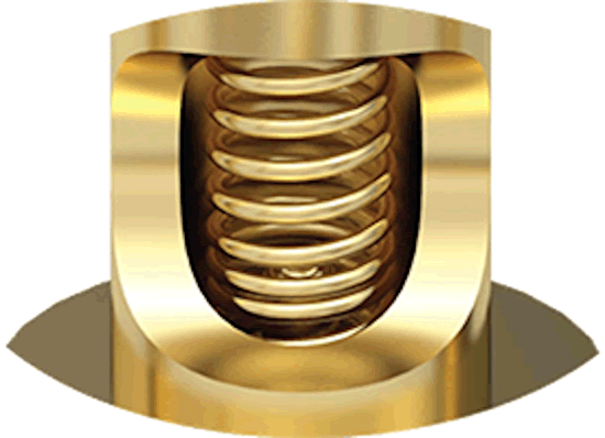
Spring-loaded pins are typically comprised of three or more machined components that are assembled with an internal spring to provide the range of movement required. All of these components are electroplated with gold over nickel to ensure excellent electrical conductivity, durability, and corrosion protection throughout the life of the product. Beyond the basic electrical requirements of voltage capability, current handling, and contact resistance of the spring-loaded pin, there are many options that require consideration when specifying SLCs.
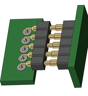
While vertical mounting is the most common arrangement, certain applications require the horizontal mating of two or more boards. Right-angle pins and targets are available in both through-hole and surface-mount configurations on a 0.1” (2.54mm) or 0.05” (1.27mm) pitch to offer a reliable, low-profile solution to this challenge. SLCs are often required to carry both power and signals within the same assembly. Standard power pins can carry currents up to 9A with a 10°C temperature rise above ambient (20°C). In applications where higher current or lower temperature rise is required, pins may be doubled up, or larger pins can be specified, especially for ground connections.
By specifying spring pins with different lengths and plunger travel in an array, so-called make-before-break connections can be created. These are especially useful in applications where power needs to be applied to a circuit before signal connections in order to avoid undefined states that can cause erratic circuit behavior. These connections also allow key signals to mate sooner or later based on the requirements of the application.
Depending upon the mechanical configuration of the application, different travel distances may be required, along with custom spring forces. Most SLCs typically offer 60g of force at mid-stroke, although alternate springs are readily available. For complex, multi-board assemblies, double-action SLCs are available. Once these are fitted to the middle board in a stack, boards can be easily and conveniently mounted above and below.

SLCs are not limited to PCB-oriented applications. This versatile technology can also provide connectivity for wire termination via pins with solder cups or crimp barrels. Various sizes are available offering the ability to accommodate wires up to 16AWG, with 9A current-handling capability. SLCs with a high-temperature Nylon 46 insulator that is compatible with most soldering processes are available for connections that pass through metallic or conductive materials, such as conductive cases or housings.
When designing-in an SLC, it is generally best to aim to operate around the mid-stroke of the travel range. Between 25–75% compression is generally recommended; although, some one-time compression applications benefit from working closer to the maximum compression. For very-low-profile spring pins with minimal stroke capability, it is best to be in the 50–85% compression range.
Spring pins are able to mate with non-parallel surfaces, but it is important to ensure that the mating force is axially applied to the piston/plunger. Lateral engagement or side-loading of the piston should be avoided, as this may cause damage to the piston or spring pin body by bending or fracturing it.
In applications where mating is less controlled, it is good design practice to incorporate stand-off hardware or other features to provide mechanical support in order to avoid over-compression of the spring pin.
One of the great benefits of SLCs is their versatility and ability to mate with a wide variety of surfaces. As long as a spring pin plunger/piston makes contact with a flat or concave plated surface, a good connection is made. This removes one side of traditional pin-and-socket connector systems and leads to cost savings in terms of component cost and production time and complexity.

While mating with gold-plated PCB pads is the most common implementation, other mechanical options are available to meet specific application requirements. For through-hole applications, a dedicated nail-head pin or target pin can be used. In surface-mount applications, low-profile, gold-plated target discs are available to provide a highly conductive, wear-resistant extension to the board surface. By combining spring pins with the appropriate target, different mating distances can be implemented to suit almost any application.
Poor quality connections, resulting from either poor design or wear and tear, negatively impact overall system reliability. As such, proven and demonstrated reliability is crucial to specifying the correct SLC for an application. IEC 60512 has been the definitive standard for testing connectors for their mechanical, electrical, and climatic properties since its introduction in 1976. The standard prescribes a number of tests to assess the quality and reliability of connectors, including spring force, contact resistance, random, half sinus and sinusoidal vibration, rapid temperature change, dry heat, cyclic heat, cold, and current-carrying capacity. These tests are extensive and are performed on virgin parts, as well as parts that have been pre-cycled, ensuring that the connectors will give long-term reliability in real-world applications. Some manufacturers use IEC 60512 as a baseline but add specific additional tests to reflect known applications or address other potential weaknesses as technology changes.
When specifying SLCs, designers should review all available test data. Reputable manufacturers will often introduce non-standard tests that are specific to certain types of connectors that will provide designers with further assurances about a connector’s ability to perform reliably in a certain application.
Another valuable criteria for selecting one brand of SLC over another is the availability of design support materials. Most manufacturers will offer multiple tools, including detailed 3D models (e.g., IGES or STEP) for rapid design mock-ups and PCB layout recommendations to ensure that the correct land patterns are implemented for optimum SLC operation.
As innovation generates new product categories, versatile SLC connectors are playing a significant role in enabling future technologies. One of the original SLC applications, and still the most popular by far, is board-to-board connectivity between two or more PCBs. As reducing product size drives space to a premium and modular approaches to design become more popular, manufacturers are increasing the number of PCBs in a product. SLCs allow for multiple boards to be stacked easily, with the SLCs accommodating tolerance stack-ups, including small misalignments due to non-parallel fixing or PCB warpage. The versatility of SLCs makes them a viable solution, whether the boards are parallel, perpendicular, vertical, or horizontal.

Limited space in today’s designs also means that blind mating, where one half of the connector cannot be seen during mating, is becoming more common. Pin-to-receptacle misalignment during engagement can lead to broken or bent pins, damaged contacts, and poor or missing connections. An SLC is an ideal solution, as there is no insertion required. The connection is made when the plunger tip contacts a conductive surface, typically a pad on a PCB or the face of a target pin. These mating surfaces are usually larger than the spring pin plunger, which further eliminates concerns about alignment and potential damage to components.
As more devices become portable, they rely on battery power and require frequent charging, often in a charging cradle. SLCs are a perfect solution for charging batteries in portable instruments, as well as docking handheld devices for data and power transfer purposes. They can be easily integrated into any system with numerous options available in terms of height, travel, and spring force. Contact is made with the plunger tip, and the spring pin allows for blind mating and some misalignment when placing the battery or device in the cradle. This makes it a good choice for applications in which end users make the connection.
Founded in 1971, Mill-Max Mfg. Corp. is the leading US manufacturer of machined interconnect components. Its full product line includes: spring-loaded connectors; SIP, DIP, PGA, and BGA sockets; board-to-board interconnects and pin headers; surface-mount and custom products; PCB pins and receptacles; and solder terminals, wrapost receptacles, and terminals.
Recently posted:
[related_posts limit=”10″]


