Cable Backplanes: Roadmap to the Future?
Cable Backplanes: Roadmap to the Future?
 The traditional daughtercard plugging into a rigid backplane has served as a near-universal system architecture of electronic systems for many years. This modular design allows a machine to be partitioned into functional subassemblies that provide efficient electrical point-to-point or bus-structured interconnect between daughtercards. Pluggable daughtercards simplify manufacture of complex systems, facilitate field repair, and allow the system to be upgraded by simply replacing the daughtercards. Unused slots in the backplane can be populated to scale the system up to support expanding needs. Copper traces buried in a multi-layer backplane can be carefully designed to maintain impedance control as well as minimize crosstalk, attenuation, and skew. A host of backplane connectors that range from one-piece edge cards to high-performance two-piece pin-and-socket designs are available.
Unfortunately, the laws of physics begin to intervene as data rates increase. Signal integrity deteriorates when frequencies reach into the multi-gigabit range. The degree of high-speed signal distortion becomes significantly greater as channel lengths become longer. Reducing the physical distance between daughtercards becomes a priority.
Signals in a typical channel must travel through some length of daughtercard, over a backplane connector, cross from one end of the backplane to the other, through another backplane connector and over more daughtercard to its destination. Large card cages may result in card-to-card backplane links that reach to one meter or more, exacerbating the problem. Active signal conditioning technology such as pre-emphasis, equalization, and retimers, along with the use of printed circuit board materials with enhanced electrical characteristics, have been incredibly effective in enabling 10 Gb/s signaling, but the added cost and power consumption is problematic. As system speeds exceed 10 Gb/s data rates, signal integrity problems are pushing designers to explore alternative designs.
 One solution has been the adoption of a cardcage architecture that reduces the length of the interconnection between daughtercards. Midplane designs move the backplane forward, allowing daughtercards to be plugged from both sides, effectively reducing the board-to-board circuit path length. Equipment designed around a midplane design must allow card access from both the front and rear of the card cage — not an attractive requirement where racks of equipment are tightly packed. Midplane designs may require traces on the backplane to any daughtercards not mated in line.
 One solution is to rotate the mating direction of the rear daughtercards 90°, allowing direct connection through the midplane between all cards in the rack.
Orthogonal architecture comes in two flavors — midplane and direct. Typical orthogonal midplane designs utilize special feed-through headers that accomplish the 90° rotation as signals pass through the midplane, reducing the daughtercard-to-daughtercard circuit length to a minimum. This is particularly useful in full mesh network applications.
Since the midplane is utilized only for low-speed and power distribution circuits, lower grade PCB material can be used. Reduced layer count and simplified circuit layout can further minimize the total cost of the system. Challenges imposed by orthogonal midplane systems include providing adequate cooling airflow to cards in 90° orientation that are separated by the midplane.
 Several years ago, Molex introduced a direct orthogonal interconnect system that allows daughtercards to mate directly with each other, completely eliminating the midplane. Several suppliers continue to explore direct orthogonal interconnects that can address the serious mechanical alignment and support issues involved. Direct orthogonal systems may be limited in daughtercard size and pin count due to accumulating tolerances and insertion forces.
As system speeds start to approach the next plateau of 25 Gb/s, channel length limitations inherent in propagating differential signals through even high-performance PCB laminates become severe. One emerging solution bypasses the backplane replacing copper traces with discrete shielded twinaxial cables. High-speed signals from daughtercards are passed directly through a modified vertical backplane header to a series of shielded differential cables that provide point-to-point links among the daughtercards. Insertion loss, impedance, crosstalk, and skew can be managed more efficiently in cable than in the highest performance PCB laminate. Systems designed around cable backplanes can utilize lower cost backplane connectors to transmit low speed signals and power. Reduced insertion loss offered by twinax cable allows high-speed signals to be propagated three to five times further than in high-performance laminate material. This is particularly important in leading-edge systems with many large daughtercards, where channels operating with picosecond rise times in single digits reduce maximum circuit path length to inches.
The evolution of cable backplanes has accelerated over the past year as OEMs press suppliers for cost-effective bandwidth roadmaps to support ever-faster system speeds. The specific process of implementing a cable backplane is highly application-specific and also influenced by manufacturing capabilities of the customer. Issues including the construction of the twinax cable, cable length, and termination method vary widely. In some cases, a long-posted backplane connector is simply pressed into plated thru-holes and a cable receptacle is mated from the rear to the extended tails. Several suppliers have tooled modified headers that are designed to allow automated termination of the cable directly to the header. Some designs mount the cable connector through an aperture cut in the backplane and utilize various styles of mounting hardware that provide connector float to compensate for daughtercard alignment tolerance. Other approaches replace the backplane with a sheet metal or cast aluminum bulkhead on which the cable backplane connectors are mounted. It may be a while before an optimal configuration emerges, but in the meantime, the extreme degree of customization makes connector manufacturer involvement early in the design stage more essential than ever before.
All four leading high-performance backplane connector manufacturers are actively developing cable backplane interconnect systems.
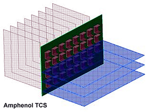
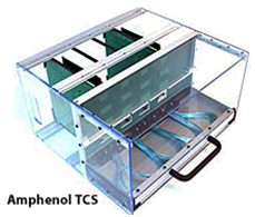 Amphenol TCS has been building cable backplane systems for five years with GbX backplane connectors and externally and internally sourced twinax cable. They recently demonstrated a new design based on the XCede connector family that features a unique cable tray mechanism to assist in the management of discrete twinax cables.
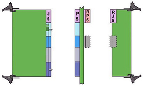
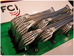 FCI Electronics has partnered with 3M Interconnect Solutions to create a cable backplane system based on the new FCI ExaMAX 25 Gb/s backplane connector and 3M ribbon twinax cables at the rear of the backplane. This concept utilizes a modified ExaMAX backplane connector that allows termination of the twinax cable to individual wafers. The connector and cable assembly is inserted into a cutout in the backplane and secured by a secondary latching assembly applied from the front. Daughtercards mate directly with this assembly.
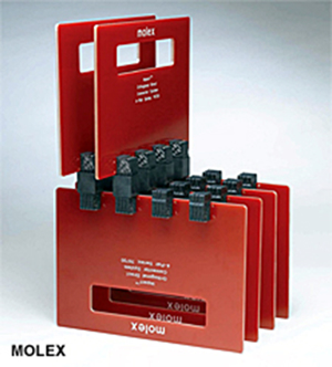
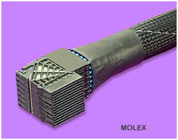 Molex has built cable backplane assemblies using their UHDM, GbX, and Impact high-speed backplane connectors. These assemblies mate with long-posted vertical headers mounted in the backplane. Twinax cables are provided by Temp-Flex, another Molex company. This internal sourcing allows Molex to control quality and cost as well as direct future product development efforts.
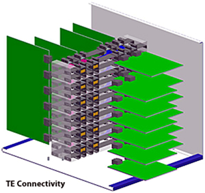
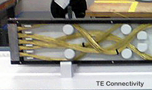 TE Connectivity has built cable backplanes using its Strada Whisper connector family. Discrete twinax cables are directly attached to the back of a vertical daughtercard header mounted in a sheet metal structure. This allows the connector to float in two axes to compensate for mechanical tolerance buildups that could put stress on the contacts.
Since the value of the twinax can become a significant factor in the overall cost of a cable backplane, the use of Madison Cable as an internal source allows TE to minimize the impact.
TE Connectivity is also in the process of developing an orthogonal cable midplane system.
Since this concept eliminates the midplane barrier, it allows for large openings that can simplify the air cooling strategy. Fewer fans may be required and dead air spots are reduced, which can reduce the overall power consumption of the unit.
We may be several years away from broad market adoption of cable backplane and orthogonal midplane systems, but interest is growing rapidly. The laws of physics that impact the high-speed performance of copper conductors are causing system designers to consider new options.
Cable backplanes were prominently displayed at the recent DesignCon 2013 conference and are quickly becoming a viable option for packaging next-generation equipment. System designers are recognizing the challenges of 25+ Gb/s systems and want to be assured that a practical roadmap to achieve ever-increasing data rates will be in place when the need exists. That is why cable as well as fiber optic backplanes continue to be the focus of advanced technology development and investment.

- Optics Outpace Copper at OFC 2024 - April 16, 2024
- Digital Lighting Enhances your Theatrical Experience - March 5, 2024
- DesignCon 2024 in Review - February 13, 2024
