A Peek Under The High-Speed Hood
Facing the growing complexity and levels of vehicle wiring for high-speed train sets, one must possess a renewed awareness of the needs and demands of each unique — yet integrated — perspective driving train set capabilities for the 21st century.
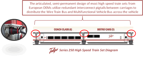
 As depicted in the systems drawing above, accommodations for components beyond “basic” train operation, such as GPS, video cameras/DVRs, Wi-Fi LAN applications, and communication — all supporting both operational and passenger expectations, along with passenger entertainment options — have become the new standard in high speed and intercity passenger vehicle design.
At the heart of this system is the train control network (TCN).
The TCN is the primary wiring scheme used in most modern train control systems, connecting the vehicle components and carriages via an 18-pin UIC 558-specified connector and cable assemblies. The TCN is composed of two major sub-systems:
Wire Train Bus (WTB)
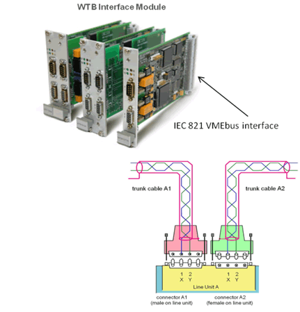 The Wire Train Bus, passing through the entire train to facilitate control and diagnostic data, is supported via a shielded twisted-pair cable or optical glass fiber. The standard WTB connection is through the UIC 558 connector using a shielded twisted-pair cable. The physical level uses digital RS-485 transmission at 1Mbit/s data rate, which allows typical system response times of 100µs.
Multifunction Vehicle Bus (MVB)
The Multifunction Vehicle Bus, an internal vehicle system connected to the WTB, can be supported via a non-shielded twisted-pair cable or optical glass fiber. Unlike with the WTB, there is no requirement for a single connector standard for the MVB inside a train set. Alternately, there are three pre-defined interconnect types used, depending on the actual application at hand: 1) Optical glass fibers (OGF) for distances up to 2,000 meters; 2) shielded twisted pair via RS 485 (EMD, electrical medium distance) for allowable lengths of up to 200 meters; and 3)simple backplane wiring (ESD, electrical short distance without galvanic isolation). This cable may reach 20 meters in length, using two 9-pin Sub-D connectors, one male and one female per system device/module.
Despite the documented advantages of the MVB, many train vehicles are still built on CANopen and Profibus platforms. As additional functionality is added to rail vehicles, bandwidth demand begins to exceed what these field buses can support. IP applications via Ethernet are finding their way into modern train sets, as defined by the EN 501555 standards profile. Either way, any operational alternate vehicle bus is ultimately connected to the Wire Train Bus.
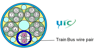
The International Union of Railways (UIC) had initially specified a cable of 13 individual conductors for this wiring scheme, but that standard now has been expanded to a total of 18 conductors. The current 18 circuit design has been arranged in such a way as to mate with the original 13-circuit version for full backward compatibility.
 The power for lighting, air-conditioning, and electric outlets for passenger use is carried by a separate cable. This cable carries single-phase 1500 volts AC @50Hz,using the tracks as the ground connection. This voltage is usually supplied from the locomotive, or in some designs, each carriage supplies its own power via a generator.
In order to use locomotive-supplied power, each carriage must be equipped with a transformer, which reduces the voltage feeding a distribution panel — which in turn supports individual applications: heating/air-conditioning, lighting, AC outlets, and infotainment systems.
The last of the 18 conductors, identified above as the Train Bus wire pair, is used for remote-control access of a second locomotive integrated into the train set at the opposite end from the head unit. This configuration is known as ”push-pull.” Depending on the direction the train must travel, either engine can supply power without the need for turning the entire train around.
In some applications, the push-pull function is accomplished via a hybrid car that has both a driver’s cab and passenger seating in lieu of a second locomotive.
Beyond the operational demands of the train set are the ever-increasing passenger comfort systems being integrated into virtually all high-speed and intercity rail services. Each of these systems — infotainment, Wi-Fi, and power distribution — require separate and appropriate cable and interconnect schemes driven by industry accepted practices or standards.
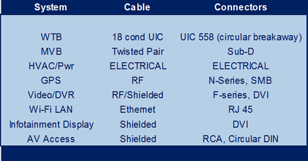
Expansion of in-vehicle infotainment introduces Ethernet into train set design as the current IP network choice. In many design schemes, individual Ethernet distribution systems are installed in each carriage to deliver entertainment and communication options to the passengers, as well as to collect operational data from the vehicle itself, ultimately reporting these collected packets back to a central operational location for analysis.
Current designs for high-speed train sets integrate the use of both off-the-shelf cable and interconnect devices in tandem with application-specific versions. The diversity of application within the high-speed train set demands the use of RF, shielded, and unshielded twisted pairs — as well as industry-specified composite cables, many of which feature zero-halogen jacket construction to meet current passenger safety standards.
The high-speed train set appears, with its sleek outer shell and color schemes, to be the most sophisticated form of land transportation on the planet. Deep down inside, we now recognize that the train set is composed of interconnects and cable of complete familiarity and accessibility at all levels of the connector industry supply chain.
- Satellites and 3D Radar Will Drive the Aviation Evolution - October 6, 2014
- Regenerative Braking Systems in Rail Applications - February 13, 2014
- Reinventing Your Wheels: Auto Convergence Technology - November 18, 2013
