Choosing the Best Components for a Wireless Network
By choosing the best components for a wireless network, says David Burrell of Phoenix Contact, it is possible to reduce the installation time as well as the risk of problems during installation.
As the demand for lower operating costs in plant facilities increases, operations personnel need to seek out and learn new ways to meet these demands.
Wireless technology has become a leading method of reducing operational expenditures. Installation costs of cabled systems as compared to wireless systems can increase material and installation costs by up to 500%, or even more in hazardous areas. Because of this, suppliers have seen a rapid increase in the market acceptance of wireless, resulting in the development of new wireless technologies and standards specifically designed to meet industry needs.
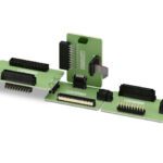
While the focus of most discussions about the usage of wireless technology is on the radio device itself, it is important to remember the installation practices and auxiliary equipment of those networks also play a major role in the reliability of an installed network. Low-quality accessories, such as antennas and coaxial cables, coupled with poor installation are some of the most common causes of failure in a wireless system.
Power Measurements
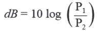
Electric power is typically referred to as decibels (dB). A dB is an abbreviation for a power ratio calculated using the formula below with both P1 and P2 being of the same power unit.
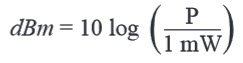
In wireless communications, power is referred to as dBm. A dBm is calculated the same as a dB although P2 always equals 1mW.
Some very common powers in wireless communications are found in the table below:
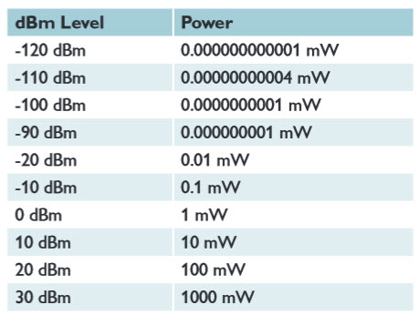
The effect of power is doubled for every 3dBm gain in commonly referred-to power levels in the wireless industry. An increase of 6dBm results in doubling the effective line of sight range of a wireless link.
The abbreviation dBi is used for gain of isotropic antennas. An isotropic antenna radiates equally in all directions. dBi and dBm can be added mathematically. The resulting number is in dBm.
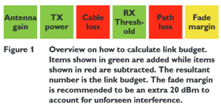
Link Budget
A link budget of a radio path is the sum of all antenna gains, cable losses, radio transmission power, receiver sensitivity, and path loss (how much signal is lost from the transmitter to the receiver due to obstructions or free space).The remaining signal level is called the fade margin, the “cushion” between the received signal and the minimum receive threshold of the radio device. A 10-20dB fade margin should be calculated into the link budget of the path in order to compensate for environmental changes that could attenuate the signal being transmitted. The fade margin can be increased by using higher-gain antennas and lower-loss coaxial cable, or increasing the transmission power when possible. Figure 1 shows an overview of the calculations.
Antenna selection
The single most important item affecting radio performance is the antenna system. Without careful attention to this part of an installation, the performance of the entire system will be compromised. The antennas should be specifically designed for use at the intended frequency of operation and with matching impedance. Select an antenna with an appropriate gain for the path for which it will be used.
Polarization of Antennas
Polarization is a fundamental characteristic of an antenna. It is the direction in which the energy from the radio is emitted from an antenna through space. Antennas can be polarized in three different ways – vertically, horizontally, and radially. Cross-polarizing antennas of a wireless system will result in only a fraction of the transmission power being accepted at the receiver. The fraction of the emitted power that is received depends on the angle between polarization of the antennas in the system. If an antenna is 90° out of phase, no power will be received. If an antenna is 45° or 135° out of phase, only half of the power will be received. This is the reason proper installation of antennas is so important.
For omni-directional antennas to be horizontally polarized, they need to be mounted perpendicular to ground level, whereas a yagi-directional antenna needs to be mounted parallel, or flat, with ground level to be horizontally polarized.
Cross polarization can be beneficial: If two networks in the same operating frequency are installed in close proximity, and interference is a resulting factor between them, it is possible to change the polarization of one entire network to overcome intrusive signals between the two networks.
Universal Antenna Characteristics
Omni-directional antennas: Omni-directional antennas usually are used if the position between the transmitter and the receiver can change, moving applications or, for example, creating a multipoint network. Omni-directional antennas have almost uniform directional characteristics over a 360-degree horizontal plane (Figure 2).
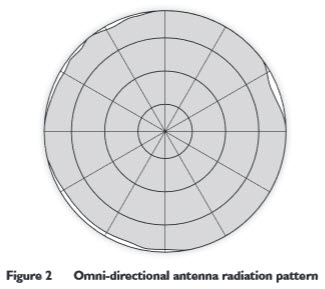
Omni-directional antennas are also recommended for applications with obstructed lines of sight because in such cases, the signal can travel from the transmitter to the receiver via reflections.
The ideal installation location is the top of a mast or on a control cabinet, so that the antenna has the greatest possible free space in all directions. Unfortunately, it is not always possible to mount the antenna in these locations. If an omni-directional antenna is mounted on the side of a mast, specific measurements and distances must be observed.
Any conductive material to which an antenna is mounted, such as a master control cabinet, affects the directional characteristics of the antenna. Depending on the diameter and distance between the antenna and the conductive material, the antenna’s area of coverage may be significantly altered. As a result of this, wall mounting should be avoided as the wall has a great impact on the transmission properties of the antenna. If a wall mount must be used, it is important to provide, at minimum, half a wavelength of the respective operating frequency of distance between the wall and the antenna.
Yagi-directional Antennas: Yagi-directional antennas radiate power in a specific direction, allowing greater communication range and reducing the chance of interference from other users outside the pattern. Figure 3 shows an example of a Yagi radiation pattern.
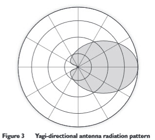
As the gain of a Yagi antenna increases, the energy becomes more focused, causing the beam width to decrease, thus making proper alignment more critical. It is necessary to aim these antennas in the desired direction of communication, i.e., directed at the master station. A directional antenna is recommended at remote fixed stations when covering large distances with line of sight. The end of the antenna (farthest from support mast) should face the associated station. A master location with multiple slave radios must always have an omni-directional antenna, and the slave radios may have Yagi-directional antennas to increase distance possibilities. Final alignment of the antenna heading can be accomplished by orienting it for maximum signal strength.
With directional antennas, it is particularly important to ensure that the antenna is mounted securely. An unstable antenna may “sway” or “wobble” in strong winds, which can cause gross misalignment of antennas.
Antenna Cables
The importance of using a high-quality antenna coaxial cable is often neglected during radio installation. Using the wrong cable can cause huge reductions in efficiency or even damage the radio.
For every 3dB of coaxial cable loss, the transmission distance is reduced by half. The choice of coaxial cable to use depends on:
- The length of cable required to span the distance between transmitter and antenna
- The amount of signal loss that can be tolerated
- Cost considerations
For long-range transmission paths, where signal is likely to be weaker, a low-loss cable type is recommended, especially if the length of the cable must exceed 50 feet. For a short-range system, or one that requires only a short antenna coaxial cable, a less efficient cable may be acceptable, and will cost far less than large-diameter cables.
The amount of loss introduced by the cable is also frequency-dependent. As the radio operating frequency increases, the cable loss will also increase. Check coaxial cable datasheets carefully to determine their suitability for a specific radio frequency.
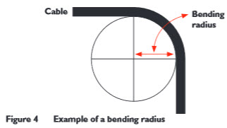
For installation purposes, the bending radius of a coaxial cable must be taken into consideration. The bending radius is the minimum radius to the inside curvature of the cable without kinking, damaging, or shortening its life span. An example of “bending radius” is shown in Figure 4. The bending radius of a cable is typically identified on the datasheet.
Power Supplies
Power supplies are often overlooked during the planning of a radio site. A radio device has some operating modes or periods that demand a high amount of power. The installed power supply must be able to provide enough current to all the connected loads, while having at least 30% overhead to compensate for expansion and loads that can draw variable power.
Without a sufficient power source, a radio will not operate correctly. This can result in intermittent radio links, dropped data, or resetting devices. For high integrity sites, it is the installation of a UPS for a backup power supply in case power fails at that site is also recommended.
From planning to installation, when the single most important goal is a high-quality network that will last longer and provide the most reliable results, choosing components is equally as important as choosing the main system.
To read this white paper in its entirety, click here.
[hr]
David Burrell is a wireless product specialist, I/O and networks, for Phoenix Contact Americas.