Derating Wire Harnesses Can Achieve Weight, Space, and Heat Goals
Designers can use derating to capture the advantages of lighter-weight wires without sacrificing performance.
By Michael Traskos, EWIS Designated Engineering Representative (DER) and President, Lectromec
By derating wire harnesses, designers can expand their options to choose materials that can perform in a greater range of applications and environments. The temperature rating of a wire limits the amount of electrical current that can be transmitted down the wire before it heats up beyond its temperature rating. When there are multiple wires in a single wire harness in addition to supporting equipment like clamps and other parts of the electrical wiring interconnect system (EWIS), such as connectors and secondary harness protection, the full environment in which a wire harness operates becomes thermally complex. However, by derating a wire harness, it’s possible to come up with an implementation solution that achieves a good balance between weight reduction and heat reduction goals.
What is the Benefit of Derating?
The chief purpose of derating is to avoid using too large a wire gauge, as this adds unnecessary weight to the vehicle. For example, decreasing the wire gauge size from 8AWG to 10AWG for 20 feet in a given wire harness can reduce the weight by more than half a pound, and the overall impact on a vehicle’s design can be much greater if the same derating principles and evaluations are applied to all of its wiring harnesses.
Two design elements that this can have an especially noticeable impact on are wire routing and connector size. Using smaller-gauge wires allows for a tighter bend radius and use of smaller clamps, and using smaller connectors helps reduce the total footprint of the harness and can even allow for more circuits to be run through the same or an even smaller footprint than before.
Harness Derating
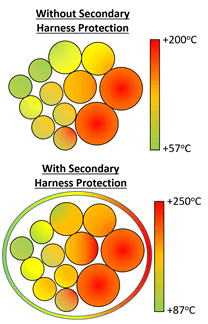
Given a wire harness configuration, what can be done to determine the derating? The conservative approach would be to use the SAE aerospace standard AS50881 for guidance. However, if additional secondary protection is placed onto the wire harness — such as Nomex braiding, chafe protection, etc. — the rate of thermal energy loss from the wire harness is impacted, and the existing guidance does not provide any feedback on how to address this.
Currently, there are two ways in which this can be addressed: laboratory testing and numeric simulation. Models for thermal derating also exist, but validation of these models still remains a question. A formal lab test will give designers the answers they need to make critical decisions about materials with full confidence.
Design

Wire temperatures in harnesses both with and without secondary harness protection.
The first step in the overall process is to understand the harness configuration. Does the wire harness contain only a few wires or is it a complicated harness set with tens or hundreds?
The next step requires understanding the environmental conditions in which the harness is placed. Is there airflow in this location? What is the ambient operational temperature? Is the environment temperature and pressure controlled? Each of these factors requires consideration and has an impact on the energy loss during operation.
System Level
Once the physical layout of a harness is understood and the environmental conditions are identified, the next step is to understand the circuit configuration. The first consideration is to identify the number of power-carrying wires and quantify the current carried by these wires. As with a load analysis for an aircraft, it’s important to know if these systems will function simultaneously. If it’s unlikely or impossible for all of the circuits to be simultaneously active, then this needs to be a consideration with the derating and test harness setup. Otherwise, the derating factor will be very conservative and require the use of larger gauge wires than is necessary.
Connector Derating
Connector derating remains ambiguous, so it’s often difficult to identify a good set of guidelines. Assume you have a 10-pin connector with contacts sized for 16AWG wire and each of the 16-gauge wires are independently able to handle 10 to 15A. The harness derating would reduce the overall power carrying capacity of a 10-wire, 16AWG wire harness, but the harness derating does not specify what derating factors are necessary for the connector derating. The difficulty with defining a standard degrading factor for connectors is that there is such a variety in connector designs, contacts, inserts, backshell accessories, etc., which makes it hard to generalize their thermal dissipation. For example, if a connector is mounted on a structure, the thermal conductivity of aluminum and composite structures are significantly different.
A white paper from TE Connectivity begins, “Can a contact rated at 10A carry 10A? Maybe yes, probably not.” Obviously, this is not very reassuring to those that rely upon the performance of electrical components at their maximum operating capacity. However, like harness derating, this can be evaluated in a laboratory environment in such a way that data can be provided to support certification efforts. To do the testing and to do it well is important to ensure the reliability of the installed system. This testing should consider all the factors that are mentioned in this article, as well as some system-specific needs that may be identified during the discovery process.
To get the most out of an EWIS, designers need more than a simple lookup table and generalized conservative estimates. More detailed analysis can provide dividends in terms of reduced weight, better design, and improved reliability of the system components, and the ultimate success of your design could depend on it.
[hr]
Michael Traskos is president of Lectromec, a technology and engineering firm specializing in the risk assessment of aircraft wiring systems. To learn how testing capabilities can support your certification effort for EWIS, visit Lectromec.
Recently posted:
[related_posts limit=”10″]


