End Launches Provide Transition from Cable to Test Boards
End launch connectors are intended for critical applications that require high-performance results. Bishop & Associate’s Dave Shaff looks at the technology that drives that performance and offers a primer on specification for particular applications.

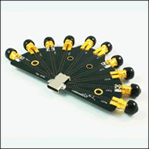
Test board with 10 SMA end launch connectors to measure output from USB 3.1 Type-C connector (Source: LUXSHARE Precision Industry Ltd.)
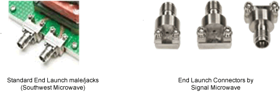
End launch connectors are used to transition microwave energy from coaxial to planar transmission-line structures. Test boards, chip demo sets, and applicable process boards use end launch connectors to connect test-line coaxial cables to grounded coplanar waveguide (GCPWG) and microstrip circuits. Chip and package testing often goes to a minimum of three times the operating frequencies to look for harmonics, which pushes demand for higher-frequency models. In-line or horizontal (where mating is parallel to board) connectors or vertical-mount designs are most common.
In 2015, the most popular higher-frequency microwave end launch connectors used 2.92mm interface (bypassing lower-frequency and intermateable versions with SMA and 3.5mm interface). These are specialized connectors produced by suppliers such as Rosenberger, Signal Microwave, Southwest Microwave, SV Microwave (Amphenol) and X-Microwave. New end launch connectors follow introductions of new standard plug/jack configurations. End launch connectors with 1.0mm interface were first shipped in 2014 and now have several sources. A 0.9mm end launch connector was released in 2015 and 0.8mm versions are underway, prompted by 0.8mm connectors in Anritsu’s newest VNAs. On the low-frequency end, test boards using end launch jacks now are available to measure performance of the new 24-position USB 3.1 Type-C connectors.
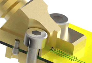
Performance is paramount as these connectors are primarily for test ports. Application success requires attention to connector design, mounting, board launch layout (including trace and ground locations), plus PCB material and thickness. Simulation software should review connectors concurrent with PCB material options. Lower-frequency applications, perhaps to 6GHz, may use adaptations of regular commercial connectors and usually are terminated by soldering to board. Higher-frequency end launch connectors, typically 8GHz and above, usually do not involve solder as termination is achieved by compressing the pin or probe-tip onto the circuit pad when the connectors are screwed down to the board.
Although performance differs due to the connector’s internal design, many producers of horizontal-mount end launch connectors for microwave and millimeter wave applications have models with common mounting dimensions. These suppliers include GigaLane, JAE, Rosenberger, Signal Microwave, SRI Connector Gage, Southwest Microwave, and X-Microwave.


Examples of lower-cost end launches with brass housings, SMA typically <12GHz (Source: Amphenol, left, and Hirose Electric, right)

Angled launch connectors with pin-to-board termination (Source: Rosenberger)
Horizontal mounting (i.e., mating cables are parallel to plane of the board) is popular, but in many applications it is being replaced by vertical-mount launches that have lower pricing (usually the result of having fewer components) and smaller board footprint. Angled and vertical launch connectors solve the problem of getting to a mid-board location. Many designers are familiar with field-replaceable jacks that involve separate loose-pin accessories. While termination of most end launch connectors for 6GHz and below involves soldering, higher-frequency vertical launch connectors are different and incorporate one-piece contacts for lower-loss, non-solder compression-probe termination. Benefits of solderless termination include reduced installation time, faster inspection, and the ability to remove/reuse the connectors without being reworked. Vendors of lower-frequency vertical launch connectors (e.g., MMCX, SMA for <6GHz, etc.) include Amphenol, Cinch Connectivity, Corning Gilbert (primarily GPO/GPPO), Johnson (Cinch Connectivity), GigaLane, HUBER+SUHNER, and TE Connectivity. Current suppliers of higher-frequency vertical launch connectors (e.g., SMA at 27GHz, 2.92mm, 1.0mm, etc.) include Molex, Signal Microwave, SV Microwave, and Rosenberger.
Circuit materials are available in a wide range of thicknesses. Once a material has been selected for its electrical performance, the thickness is usually a function of the optimum circuit dimensions for a given frequency range since thinner printed circuit board (PCB) laminates yield finer conductor widths for a given relative dielectric constant. Thinner circuit boards may be attractive for their light weight and compactness, but fabricating finer circuit dimensions is expensive and many board suppliers do not offer the necessary microwave materials.
The transition from a waveguide or coaxial connector to the PCB is critical to the performance of the circuit, and the PCB’s thickness impacts how the transition is made. Waveguide and coaxial connectors come in many shapes and sizes, as do PCB thicknesses, and matching the connector to the substrate thickness plays a large role in overall performance. Using non-microwave board materials such as FR4 for signal circuits in multilayer stack-ups along with microwave top layers (such as Rogers R4008) poses additional problems for use with end launch connectors, sometimes requiring partial back-drilling under the connector center pin termination to maintain 50-ohm conditions.
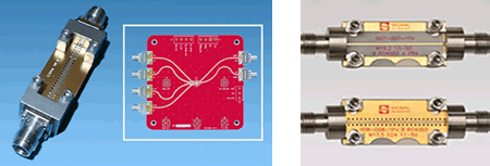
Vendor test data must be studied to determine what actually has been tested. Was it a back-to-back connector pair or does the data include the launch-to-board and board itself? Many microwave connectors appear similar, but internal design and production tolerances result in significantly different performance and costs. For example, some manufacturers’ SMA end launch connectors are specified for 6GHz, although the supplier also says it is “compatible up to 20GHz,” while SMA end launch connectors with test data that confirm 26.5/27GHz results are marketed by others. Some suppliers offer test boards (usually one inch long) that can be used to test incoming end launch connectors for consistent performance. (These boards are not optimized for any specific application, but they provide a known reference to check consistency of connector performance.) Users need to understand the cumulative effects of both input/output terminations, connector-to-board launches, and board/circuit losses. The more knowledgeable suppliers offer suggestions for board launch design and can provide simulation results for custom applications.

Measuring connectors on standardized test boards confirms consistent connector characteristics.
Studies have shown that best electrical performance is achieved by optimally matching the dimensions of an end launch connector’s (rear launch) pin to the thickness of the PCB material, with smaller-diameter launch pins for thinner circuit materials and larger launch pins for thicker circuit materials. Dynamics between edge-launch connectors and PCB materials with different thicknesses are described in a study performed by Southwest Microwave, entitled “The Design and Test of Broadband Launches up to 50GHz on Thin and Thick Substrates” and authored by Bill Rosas. This report explains why the same series connectors (e.g., SMA or 2.92mm or 1.85mm, etc.) are offered with multiple rear-pin diameters. For the dielectric constant of the materials studied, circuit materials thinner than 8mils resulted in extremely fine-width circuit dimensions, while materials thicker than 30mils suffered higher losses, at 50GHz. Dimensions and design (trace taper, ground connections, and via locations, etc.) of a coaxial launch should be studied and then matched to the thickness of the circuit substrate.
End launch connectors are intended for critical applications where best performance is desired. They should be specified with the same care used for VNA and other expensive test cables. Selection involves concurrent study of launch layout (especially options for grounds), board materials and layers, frequency, and reuse potentials. Users should take advantage of suppliers’ reference libraries for launch data and confirm that testing includes the connector plus specific launch and board configurations. Properly used, they will enhance demo boards and optimize test output.
- New Circular Connectors Add to Multi-Billion Dollar Market - January 9, 2024
- Counterfeit Components Ground Airlines - December 12, 2023
- Cables, Connectors, Waveguides, and Hybrid Products for up to THz at IMS 2023 - July 11, 2023


