Facility Cabling Systems and Increased Healthcare Data Requirements
As patient records, diagnostic information, and even the operating theater increasingly rely on networked electronics, the amount of data that must be managed has grown dramatically. Here we’ve excerpted a detailed white paper by Berk-Tek Leviton Technologies on some of the available solutions for increasing speed and efficiency in a facility’s cabling infrastructure.
Hospitals and other healthcare providers face the daunting challenge of managing information. As patient records, diagnostic information, and even the operating theater increasingly rely on networked electronics, the amount of data that must be created, transmitted, managed, and stored has grown dramatically. In addition, regulations requiring high levels of data security to protect patient privacy add an additional layer of complexity to information management.
To meet these challenges, healthcare facilities are focused on two main network improvements:
- Higher bandwidth – From transmitting MRI images to video consultations, networks must work at higher speeds to deliver services. Networks are looking to support 10Gb/s speeds in critical areas, with 40Gb/s or 100Gb/s in the core to ensure bandwidth availability.
- More connections – As more and more equipment is network-enabled, more network ports must be provided for users. The port density in any given area depends on the area’s function, but network administrators are learning a few extra ports are better than too few. More connected equipment also means more bandwidth is needed.
Standardizing Cabling for the Healthcare Environment
The network is vital to today’s healthcare facility, and higher data rates are required to handle growing demands on the network. The right structured cabling system must be designed and installed to meet these realities. ANSI/TIA-1179, the Healthcare Facility Telecommunications Cabling Systems standard, addresses the special requirements of cabling systems in healthcare facilities.
There are generic standards to address the architecture of the cabling system and recommend best practices for cross connects, cabling distances, and cable and connector performance specifications. ANSI/TIA -568-C is the primary example of a generic standard whose recommendations form best practices for cabling systems.
A typical network in a typical business is largely a cookie-cutter affair. With some exceptions, all work areas have the same network connectivity. Businesses standardize to provide the same connectivity to each office. Schools similarly standardize classrooms. Likewise, chain stores often install the same network in every new store. Variations tend to be small – four data ports instead of two. Generic cabling standards, like ANSI/TIA-568-C, rightly recognize that an extremely wide swath of applications can beneficially adopt similar standards.
Hospitals and other healthcare environments do not fall under this cookie-cutter approach. For example, different areas of the hospital have significantly different connectivity needs. Office areas may require four ports, exam rooms 10 ports, MRI suites 20 ports, and operating rooms 40 or more ports. As a result, the TIA issued ANSI/TIA-1179 to address the specific needs of healthcare facilities.
Work Areas
ANSI/TIA-1179 recognizes hospital and healthcare facilities have different needs in the number of network connections required and the related density of cables run to a multitude of areas.
The standard identifies 11 application-specific types of work areas:
- Ambulatory care
- Caregiver
- Critical care
- Diagnostic and treatment
- Emergency
- Facilities
- Operations
- Patient services
- Service/support
- Surgery/procedures/operating rooms
- Women’s health
Each of these work areas has further subareas with varying cable densities, yielding about 75 areas. To paint with a broad stroke, areas dealing directly with patient care and treatment have higher cable densities than areas dealing with administration or facilities.
The table below summarizes the cable density recommendations of ANSI/TIA-1179. While an area with 14 outlets is considered a high-density area, that number is conservative. Some new operating rooms have upwards of 50 outlets to support the increasing needs for connectivity.
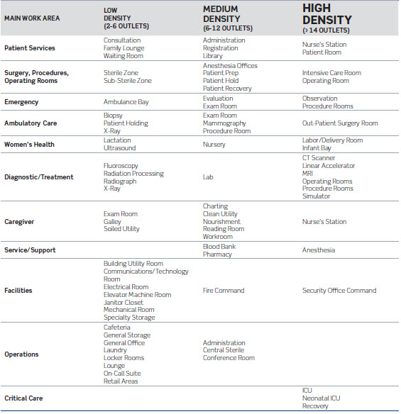
While it is normal practice to gang several ports into a single outlet, ports can be spread around the area as appropriate. For example, ports for biomedical equipment can be located on each side of a patient bed, while ports for television or other ancillary needs can be across the room and at ceiling height. In operating rooms, outlets are even included in booms over the table.
Figure 1: Color-coded outlets allow easy port identification.
Outlets in the work areas should be clearly and easily identified by function. Since most hospitals will install many separate networks – biomedical, television, phone, security, etc. – fast and easy identification is critical, especially when attaching medical equipment. The outlet jacks themselves are available color-coded (figure 1), as are snap-in icons. Visual identification is essential for end users; TIA recommends additional identification to support network administrators and technicians. For operating rooms, critical care, and other areas, stainless steel faceplates are available to make cleaning and sterilization easier.
Figure 2: MUTOAs offer a flexible approach to providing multiple outlets.
Multiple-user telecommunication outlet assemblies (MUTOAs) provide a flexible approach for areas that might experience frequent rearrangements or retrofits. These provide a centralized patching area within specific spaces that are fully accessible. Offering up to 24 ports, MUTOAs should be permanently mounted on the wall or in an architectural column. (Note that ANSI/TIA-1179 only recommends MUTOAs for retrofits, not for new hospitals).
One possible way to simplify cabling is to run multi-fiber pairs to the work area. The fibers connect to a workgroup switch dedicated to that area. The switch then connects to the individual outlets. (Theoretically, users could connect directly to the switch, but this is a poor practice that should be avoided.) While this approach drastically cuts the number of lines running from the horizontal cross connect, it doesn’t satisfy the needs of segmenting network functions, so additional cables will still be needed for building alarms, TVs, and the like. Costs also need to be considered when looking at the structured cabling deployment of running all cabling homerun to the telecommunications rooms versus extending the switching fabric to the work areas. Extending the switching to the work area will also require more advanced switch management and operations. This approach is also commonly referred to as zone cabling.
Cabling Best Practices for the Future
The varying cable densities underscore the importance of careful planning. Be generous with the number of ports made available, especially in critical areas like patient rooms or operating rooms. The trend, due to rapidly increasing bandwidth demands, is toward more connectivity, not less. Not long ago, Fast Ethernet at 100Mb/s prevailed. Today, it’s Gigabit Ethernet, with most of the market running between 1 and 10 Gigabits. As mentioned, some hospitals are planning to deploy 40G and 100G in the core (data center) for interconnecting servers and storage.
A prudent eye toward the future means installing the best cable available. This is especially important in areas dealing with patient care, from diagnostics to surgery. These areas are the ones where sufficient bandwidth capacity must be available for tomorrow’s needs.
Specifically, the following cables are the recommended choices and supported by ANSI/TIA-1179:
- Category 6A UTP can support 10G Ethernet at distances to 90 meters in the horizontal or 100 meters when considering the full channel (including patch cords).
- Laser-optimized (OM3 or OM4) multimode fiber can be used both for backbone and horizontal cabling needs. For 10G Ethernet, OM3 fiber allows runs of 300 meters, while OM4 supports 550 meters.
- Single-mode fiber is typically only used where distances preclude the use of multimode fiber, such as between buildings. The cost of transceivers for single-mode fibers is significantly higher than those for multimode fibers.
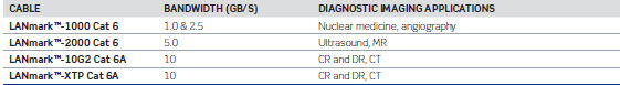
The choice of Category 6A cable over Category 6 ensures you are ready for heavy data traffic today, while equipped for migration to 10G to support future networking and bandwidth needs. With continued advancement in diagnostic imaging technologies and the growth of electronic patient records, it is safe to say that bandwidth consumption and network speeds will continue to increase over time. To avoid future mitigation, it is wise to install cable based on what your bandwidth requirements will be several years from now, rather than what they are today. Category 6A cabling is the most logical choice for the future, as it will ensure 10Gb/s network performance and provide enough bandwidth to fully support emerging technologies. The table below shows the Category 6/6A offerings recommended by Berk-Tek to support various bandwidth requirements.
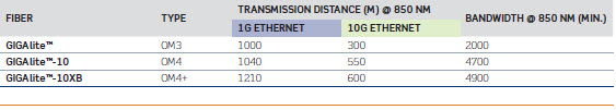
For fiber, flexible options also exist in achieving different levels of performance. The preferred choice is 50/125-µm laser-optimized multimode fiber, which is the most cost-effective option with lower-cost electronics compared to singlemode. Laser-optimized fiber is available in two performance levels, OM3 and OM4. The fiber bandwidth translates into the allowable distances the cable can be run.
Fiber optic cables can be run either as pairs or as multi-fiber array cables. Multi-fiber cables terminated with industry-standard MTP/MPO (Multi-fiber Push On) array connectors simplify use of fiber in the network. The cables significantly reduce congestion in pathways, provide the highest port densities (12 fibers in a 0.5 x 0.3-inch area), and simplify system design, installation, and management. While fiber ribbon cables are popular for array connections, reduced-diameter cables are setting a new standard in convenience. Cassette modules provide an easy breakout from the array cable to individual ports.
The network infrastructure in a healthcare facility is unique in both its requirements and its significance. In a healthcare facility, an underperforming network has more than just customer service or financial implications — it could inhibit critical patient care.
More than ever, healthcare infrastructures are burdened by exploding data storage, stringent security regulations, and ever-increasing bandwidth requirements. These challenges will only grow as technology continues to advance. Your cabling infrastructure, from racks and cabinets to cable and connectors, must not only meet today’s needs, but those evolving on the horizon.
To read this white paper in its entirety, click here.