Multi-Contact Coax Connectors and VITA Standards
Using multi-contact coax connectors and VITA standards can preserve space on the front panel and facilitate insertion/removal of cards for installation, repair, and upgrades.
 A growing trend in electronic packaging for military and aerospace applications is the availability of multi-contact coaxial interconnects. A key driver is the desire to provide RF disconnect capability at the backplane/daughtercard interface. This simplifies engagement and disengagement by eliminating the need for the cables on the front panel (top side of the daughtercard). Instead, a multi-contact module allows several contacts to be mated or unmated simultaneously at the backplane/daughtercard interface. This preserves space on the front panel and facilitates insertion/removal of cards for installation, repair, upgrades, and more.
VITA 49, for example, defines an interface between the analog and digital sections of a radio. The daughtercard-to-backplane interface marks a reasonable point for separating the two sections. The digital functions, including digital signal processing, can be done on the backplane. Analog functions are performed on the daughtercard, which can be easily swapped to accommodate different frequency spectrums and so forth. This creates a need for an easily managed and disconnected RF interface.
VITA 67
The recently approved ANSI/VITA 67 standard is an example of a modular system designed specifically to allow backplane/daughtercard multi-contact mating within a robust platform to withstand the mechanical rigors of military and aerospace applications. The VITA 67 modules are also fully compatible with VPX packaging to make it easy and convenient to achieve RF connectivity within a well-established architecture. TE Connectivity has been closely involved in VITA committees that define specifications for connectors for data, power, RF, and optical modules.
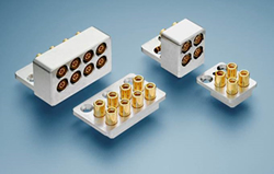
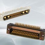
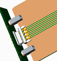
Multi-contact RF Modules (Source: TE Connectivity
High-frequency RF signals are essential to a range of mil/aero applications, including radar, electronic countermeasures, UAV electronic sensing and processing, antiballistic signal processing, and secure communications. At the same time, the ever-present impetus toward higher density packaging also drives the demand for miniature and RF interconnects. TE’s SMP and SMPM series coaxial connectors are microminiature connectors for RF/microwave applications. Both have mating interfaces controlled by MIL-STD-348. The VITA 67 standard specifies the SMPM series connector, chosen for the higher packaging density made possible by its smaller size. The goal in designing the VITA 67 RF modules was to fit eight RF contacts into the space occupied by a single VITA 46 VPX signal module. The SMPM is a miniaturized version of the SMP series connector that is 30% smaller with similar performance and has a compact push-pull blind-mate interface. While the SMPM connectors have a maximum operating frequency of 65GHz, the VITA 67 standard requirement is a frequency range of DC to 26.5GHz.
In multi-position configurations, such as VITA 67, the contacts must tolerate generous misalignment to allow blind mating and be configured to eliminate the possibility of “stubbing.” The interface surfaces must mate fully and reliably to maintain the specified electrical performance. VITA 67 modules accommodate a radial misalignment of .010 inch (0.25mm) and offer an axial float of .079 inch (2.0mm). The axial float provides the spring force required to ensure the contacts fully mate and maintain signal integrity under vibration and other mechanical stress conditions. Adequate spring force is essential to assure proper mating, sufficient normal force, and uninterrupted signal integrity.
Durability
After positive mating and alignment are achieved, the mechanical configuration must ensure contact over-travel, low insertion force, and high mating durability.
The VITA 67 contacts are housed in robust stainless steel or aluminum modules that hold four or eight contacts. Contact spacing is .240 inch (6.1mm), which represents a compromise in combining high density and electrical isolation. The modules are configured to provide RFI/EMI shielding between the contacts and provide a high level of adjacent channel isolation of at least 100dBc up through 30GHz. To put this in perspective, under similar conditions, the shielding effectiveness of a typical cable assembly is 90-100dBc. The physical configuration, electrical performance, and durability of the RF module-SMPM interconnect system contribute to the achievement of system performance that meets or exceeds the requirements of VITA 67 shown in the chart below.
VITA 67 Electrical Requirements
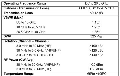
Figure 2. VITA 67 Electrical Requirements
VITA 65 Open VPX Systems
VITA 67 RF modules and contacts are designed for application in VITA 65 Open VPX systems and must withstand the robust mechanical and environmental performance requirements specified in the VITA 47-2005 standard. These requirements include signal continuity under mechanical shock and vibration, 500-mating-cycle durability, humidity, corrosion resistance, and operating temperature.
The two module sizes provide application flexibility. Four-position modules (VITA 67.1) are intended for 3U VPX, in slots P2/J2. Suited for 6U systems, the eight-position modules (VITA 67.2) can be used in slots P5/J5 or P6/J6. The image below shows the modules in a 6U system in slot P6/J6. The modules, of course, are not restricted only to VPX applications. The RF module profile is low enough to support a 0.8-inch card pitch, and the design has inspired many application-specific spin-off configurations, with RF contact counts from one to 24.
Low Transmission Loss
Eight-Position RF Module in a 6U VPX Architecture (Source: TE Connectivity)
SMPM series RF connectors are available in vertical board-mount and edge-launch versions for the backplane and daughtercard and cable-mount version for either or both mating halves. Cable options include .047-inch (MIL-DTL-17/151) and .086-inch RG-405 (M17/133) semi-rigid, conformable, flexible cable and RG-196/U flexible cable.
Recently, applications have emerged that require low-transmission-loss versions of these small-diameter cables. Traditionally, lower transmission loss was achieved by selecting a larger cable size; however, the SMPM series connector’s small size limits the maximum cable diameter that may be used. The solution is to look to technology for the answer. There are a number of outstanding sources for small-diameter low-loss coaxial cables. These low-loss cables typically use a larger center conductor and an insulator core of a material and configuration that permits a higher wave propagation velocity than standard cables with a solid insulation core.
Cable-mount backplane and daughtercard connectivity has several benefits over board mounting: The RF performance — i.e., transmission loss and reflection coefficient — achieved when using cables is superior and more predictable than that of in-board transmission line structures. The application of cables typically has a lower installed cost than multilayer RF circuit boards and are easily reconfigured, replaced, or repaired. The downside of cable configured interconnects is that overall packaging density is somewhat compromised.
New Developments
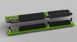
To accommodate future in-board circuit requirements, orthogonal-mount PCB backplane connectors are available in a configuration that mates with the VITA 67 daughtercard modules. Board termination is either solder or press-fit-compliant pin.
The VITA 67 working group is also working on an edge-launch version (concept shown below). An edge-launch version limits the interface to a single row of contacts. To achieve a higher multi-row density, the RF board can be stacked on the daughtercard in a mezzanine arrangement.
Edge-launch PCB daughtercard-to-backplane RF interface (Source: TE Connectivity)
Multi-contact modules, such as those offered by VITA 67, are enabling RF connectivity within a well-established industry-standard architecture. Such modules, using microminiature RF contacts, provide a high contact density at the daughtercard-to-backplane interface, while achieving the electrical isolation needed to maintain high performance levels. By offering a rear panel interface, this approach allows quick removal and replacement of cards to speed maintenance and repair.
The same modular concept can also be extended to proprietary applications requiring higher contact counts.
[hr]
 Steve Morley is a product development engineer for TE Connectivity, Global Aerospace, Defense & Marine. He has more than 30 years of experience designing, testing, and analyzing microwave and radio frequency connectors, cable assemblies, and components. Connect with Steve here.