Beyond the Connection: SFP+ Fiber Optic Transceiver Thermal and EMI Considerations
Beyond the Connection: SFP+ Fiber Optic Transceiver Thermal and EMI Considerations

Figure 1. Examples of SFP+ optical transceiver modules
High data-rate (10-14Gb/s) small form-factor pluggable optical transceivers (SFP+) answer the industry’s demand for increased bandwidth and higher port density. Figure 1 shows examples of SFP+ optical transceivers in single and multiple port configurations, including 1×2, 1×4, and 1×6 cages. The higher performance and density of these devices result in challenges related to both excess heat and EMI emissions, but there are a number of ways to address both of these operational concerns.
Thermal Performance
There are also many internal and external variables that affect thermal performance of pluggable I/O products and dictate whether or not a cooling solution is required. Unfortunately, there is no clear answer to this question and, therefore, system architects must consider many options and restrictions when designing end products.
The form factor of the product must be taken into account, as different configurations have unique airflows. A “pizza box” (whether a 1U or 4U) that is mounted in a standard rack may have front-to-back airflow or side-to-side airflow. A blade-style switch or piece of equipment may be mounted vertically within an enclosure that is in turn mounted in a standard rack. This type of configuration almost always has bottom-to-top airflow.
The number and density of ports mounted to the PCB must also be well thought-out. These ports can be single port cages, 1xN ganged cages, 2xN stacked cages, or a combination of all three. This is in addition to other I/O connectors at the face of the product. The spacing between these cages must also be taken into account, as well as port density, ambient air temperature, airflow, allowable temperature rise, and backpressure created by baffling.
Finally, heat dissipation of the optical transceiver itself must be considered. Older SFP optical transceivers usually operate at lower wattages but newer SFP+ optical transceivers operate at higher wattages. Commercially available optical transceivers are rated up to 70°C, but there are extended-temperature-range transceivers that can operate up to 85°C. Newer SFP+ modules that are used in short-reach and long-reach applications are still dissipating 1 watt or less, but extended reach and fixed DWDM (dense wavelength division multiplexing) transceivers can range from 1.25 to 1.5 watts per port.
The industry has found that trying to cool these higher-wattage transceivers in SFP+ stacked cages is quite challenging. Managing the temperature of the inner-lower row of ports that are not exposed to airflow is especially difficult.
Figure 2 shows the results of an experiment that simulated the conditions in a rack-mounted router with 24 data ports comprised of six 1×4 ganged cages. The cages are stacked in three stacked pairs. Airflow is moving across the entire assembly from left to right. Table 1 provides details of the test setup. The red numbers in Figure 1 show individual SFP+ ports that are running at temperatures in excess of the 70ºC operating limit.
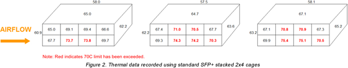
Table 1. Thermal Test Setup Parameters
| Airflow | 500 LFM (measured by airflow chamber and not by anemometer probe) |
| Backpressure | 0.25 inches of water (controlled by baffle) |
| Altitude | Sea level |
| Temperature | Room ambient (results adjusted for 55°C ambient) |
| Power | 1.5 watt per transceiver |
| Air gap above cage: | 50mm |
| Air gap below PCB: | 9.5mm |
| Temperature rise limit: | 70° C |
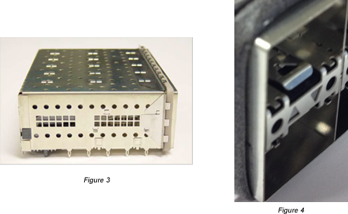
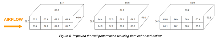
In order to improve the thermal characteristics, ventilation holes have been strategically placed in both the cage body and in the latch plate. Figure 3 shows a side view of the cage assembly that includes side-wall perforations. Figure 4 is a close-up view of the latch plate that includes the two thermal vent holes. The perforations in the cage body were optimized in size and shape in order to minimize the potential for EMI leakage. The two thermal vent holes added to the front of each latch plate still allow for the use of two light pipes.
The results of these simple modifications to the test setup demonstrate a remarkable improvement in thermal performance (Figure 5). None of the ports in the revised test exceed the 70ºC limit under identical test conditions.
EMI Emissions
Many variables affect EMI emissions, such as leakage from optical transceivers, type of board-level components (integrated chips, power supply module, etc.), and other improperly shielded connectors used in today’s communications equipment. If these EMI emissions are not properly contained within a chassis, then these disturbances may degrade or limit the effective performance of the electrical circuit or prevent the end product from passing FCC emissions standards. These effects can range from a decrease in performance to a total loss of data transmission.
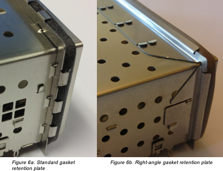
Two components have been identified that improve EMI performance. The first component is the gasket retention plate, shown in Figure 6a. This component acts as a backer plate for the conductive elastomeric gasket that interfaces with the inside of the front bezel. Modifying the gasket retention plate to provide more attachment points to the cage body reduces EMI emissions between the cage body and gasket retention plate. The redesigned “right-angle” gasket retention plate can be seen attached to the cage body in Figure 6b.
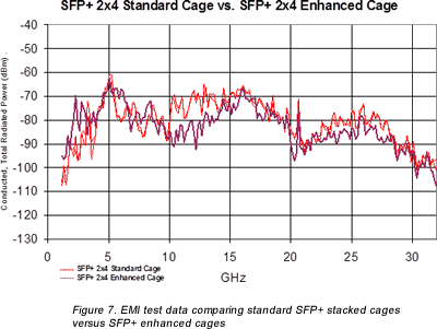
The second component identified for improvement is the latch plate, which is the component that separates the bottom port from the upper port. This component also houses the light pipes that transmit light from LEDs mounted on the PCB to the front face of the cage assembly. Industry standards dictate the design of the latching mechanism, so this was left unchanged, but within the latch plate a secondary component was added to improve EMI performance and prevent leakage. The optimization of the gasket retention plate and the addition of the component to the latch plate yielded a significant improvement in EMI performance in the 10-15 GHz range (Figure 7).
As data rates and packaging densities continue to increase, more attention must be given to containing EMI and addressing thermal considerations.
 |
David DeDonato graduated from Northeastern University with a B.S. in electrical engineering. He has been a test engineer with TE Connectivity for 25 years, specializing in thermal dissipation products and electrically conductive polymers. |
 |
Patrick Recce is a product development engineer for high-speed I/O products at TE Connectivity’s Data Communications division. He received a B.S. in mechanical engineering from Pennsylvania State University and has 15 years experience in various engineering disciplines in the electrical connector industry. He can be reached at [email protected]. |
 |
Matthew Schmitt is a product development engineer in TE Connectivity’s Data Communications business. He has 12 years of experience in the connector industry with a background in manufacturing development, product development, and sustaining engineering. In his current position, Matt focuses on high-speed I/O products like CFP, SFP/SFP+, and newer 25-100Gb/s I/O products. He holds multiple patents pertaining to EMI and thermal improvements of high-speed I/O products. |