How to Specify Coaxial Blind-Mate Connectors
In RF and microwave applications, blind-mate connections can be challenging because to maintain a constant and uniform signal between circuit boards or modules, you need specially designed blind-mate connectors. Pasternack’s Steve Ellis explains how to specify coaxial blind-mate connectors.
A blind-mate connector is used when access to the connection point is not possible, typically caused by physical space constraints. A common application for blind-mate connectors is when two circuit boards need to be mated. In RF and microwave applications, blind-mate connections can be challenging because to maintain a constant and uniform signal between circuit boards or modules, you need specially designed blind-mate connectors.
 Due to their small-footprint design and ease of connection, blind-mate connectors are often used in military applications where electronic hardware must fit into tight spaces with limited access. These connectors can also withstand harsh vibration and temperature extremes, so they are ideal for rugged field applications. Similar requirements also make blind-mate connectors a popular choice in the consumer electronics market due to the growing complexity and density of board designs. Traditionally, blind-mate connectors have been too expensive for consideration in most commercial products and therefore found limited use in commercial markets. Since the technology evolved, many connector manufacturers now offer lower-cost models designed for use up to 3GHz or 6GHz as opposed to the higher-frequency versions between 18GHz to 40GHz used in specialized applications.
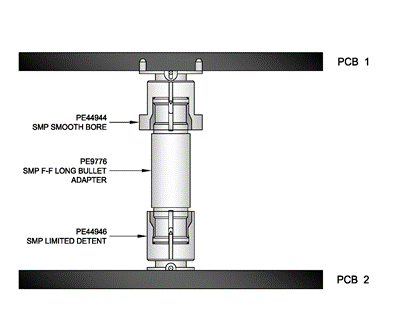
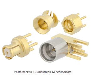
 There are many different types of blind-mate connectors available on the market today. The designs vary by size, electrical characteristics, and mechanical characteristics. There are single coaxial connection options as well as blocks or gangs of connectors built into a single housing including the D-sub connector and its many variations. The majority of the connectors are designed to be push-on connections and require some mechanical mechanism to keep the mated connectors in position. Other types include snap-on designs, which vary by the amount of force required to engage and disengage the connectors. The SMP connector (also known as Corning’s GPO connector), as well as many other popular designs, is available in a slip-on design (smooth bore) as well as limited detent and full detent options. In board-to-board applications, a typical configuration will include a smooth bore connector on the PCB, a bullet adapter, and a limited or full detent connector on the opposite PCB. Using this configuration, the adapter will remain mated to the connector with the detent capture when the boards are separated and the connection broken.
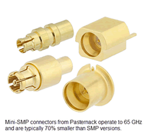
 Mechanical alignment is one of the most important properties of S connectors. SMP, mini-SMP (a.k.a SMPM or GPPO), and newer variations that work to higher frequencies allow for some mechanical misalignment. The internal construction of these connectors will allow axial and radial misalignment while maintaining the electrical integrity of the mated connectors. This is especially important as the number of coaxial connections increases. Due to mechanical tolerance stack-up, the true position and axial alignment of multiple connectors is difficult and costly to maintain, as it requires precision machining and tightly controlled manufacturing processes.
Some of the design parameters to keep in mind when selecting a coaxial blind-mate connector include physical size, maximum frequency of operation, maximum power requirements, mechanical misalignment allowed, and the number of mates and de-mates the interface needs to withstand. Here are some specifications from three different existing designs:

 Steve Ellis, interconnect product manager at Pasternack, has been involved in the RF and microwave market for more than 25 years, working as an engineer for companies such as TRW Space Systems and Hughes Ground Systems, and later moving into technical sales positions at Richardson Electronics and PCTEL. Steve joined Pasternack in 2008 and is now using his years of hands-on industry experience, product knowledge, and customer service to grow and maintain the interconnect product lines at Pasternack.


