How to Specify High-Speed Mezzanine Connectors
High-speed signal integrity concerns make choosing a connector for mezzanine board-to-board applications even more complex. Julian Ferry of Samtec offers advice on how to specify high-speed mezzanine connectors.
Choosing a connector for mezzanine board-to-board applications presents specification challenges in several engineering disciplines. High-speed signal integrity concerns make the selection even more complex.
What is a Mezzanine Connector?
First, let’s narrow the definition, as “mezzanine connector” can be a broad term. It’s generally accepted that a mezzanine connector system will connect one printed circuit board (PCB) to another PCB “inside the box.” In other words, it is most certainly not an I/O connector.
The term “mezzanine” is most often applied to PCBs that are arranged parallel to one another, with one board typically sitting above the other. However, some extend the definition to include perpendicular (right-angle) or side-by-side PCB arrangements, usually in systems with a motherboard/daughterboard arrangement.
Here, we’ll focus on the parallel arrangement. The two PCBs could be connected with a traditional two-piece separable connector, a cable assembly, flex circuitry, or a PCB riser card assembly with edge connectors. Here, we’ll focus on separable connectors.
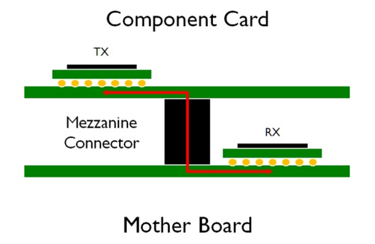
In this conceptual view of a typical mezzanine connector application, the electrical channel from the transmitter on the component card to the receiver on the mothercard is denoted by the red arrow. (Image courtesy of Samtec Inc.)
This still presents a vast array of options. How do we narrow our choices? If the application at hand is covered by an industry-standard specification, the choice is straightforward. Consider suppliers offering compliant solutions, and find the price, lead times, quality, and service levels appropriate for your needs.
If you don’t have a spec to follow, a methodical process can be used to narrow your choices to a few likely candidates. It’s often best to begin the selection process by focusing on traditional connector concerns.
Separability
An important issue is separability. Is the connection intended to be permanent? If not, how many mating cycles will be required over its lifetime? What are the minimum and maximum insertion/withdrawal forces desired?
Mechanical Requirements
Next consider mechanical requirements. Perhaps most important is stack height. This is determined by the distance between the two PCBs. Consider assembly tolerances and match them to the connector’s tolerances. It’s also important to consider the impact of other mechanical supports or constraints such as standoffs, brackets, or chassis slots and frames. Such components and features must play well together with the mezzanine connectors. 3D mechanical (computer-aided design or CAD) models of the connectors can be used to analyze these interactions. CAD models may also be useful in heat and air flow analysis, which can be critical in many high-speed system designs.
The desired board-mounting type must be determined early on: Surface-mount or through-hole? And if through-hole, soldered or press-fit?
Available footprint space on both PCBs is another consideration, along with space to accommodate mounting posts or tabs associated with the connector. If the connector supplier provides footprint data or additional trace breakout recommendations, this information can ensure signals are easily routed to and from the connectors. This is especially important with high-density array connector systems.
Performance
Other important considerations on the first-pass list include processing and operating temperature and humidity ranges, shock and vibration requirements, safety issues such as non-halogen or UL-type specifications, ROHS-compliant/lead-free standards, any unique environmental requirements, shelf life before processing, packaging, pick-and-place compatibility, etc.
Next, consider non-signal voltage and current requirements. If power is transmitted between the two boards, these requirements could be stringent. In some high-speed systems, power integrity problems can cause data transmission errors. If this is a concern, a power integrity simulation of both PCBs connected by the desired connector could be warranted.
Now, high-speed data requirements can come into play. First, determine the number of signal I/Os required, as well as the number of differential pairs or single-ended signals, if any. Any low-level or sensitive analog signals should be addressed with adequate spacing, shields, or extra ground pins.
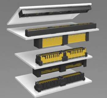
High-speed mezzanine systems are available in single-ended and differential pair configurations, with and without shielding, and in a variety of stack heights. (Photo courtesy of Samtec Inc.)
Single-ended signals might share common ground pins, but it’s best to assume each high-speed single-ended signal will require an adjacent ground terminal. If density is at a premium, a full-channel signal integrity simulation can be used to determine if ground connections can be reduced.
Potential connector choices can be narrowed by first analyzing parameters such as return loss, insertion loss, and crosstalk up to the highest frequency levels of concern. Deciding on an adequate frequency range can be difficult for digital signals. The fundamental signal frequency must certainly be addressed, but more conservative approaches extend to the third or even fifth harmonics of the fundamental.
An understanding of which electrical parameters are most critical in a particular system is important. For instance, if it’s known that a particular system is susceptible to impedance mismatch problems, return loss would be used as the highest-level filtering parameter. Or if crosstalk is more likely to cause failures, then near- or far-end crosstalk should be used as a first-pass criteria.
If an industry-standard signaling protocol is being used, some connector vendors provide application notes. These app notes provide a signal integrity analysis based on a standard-reference PCB design. A typical conclusion in such an app note would be stated as: “This interconnect system will support XX protocol at YY data speeds, with PCB trace lengths up to ZZ.” If the system will deviate slightly from the reference design, the vendor might offer a custom simulation as a support service. The reference design could also be cut and pasted into the system engineer’s preferred simulation tool and used as a starting point for further analysis.
Final confirmation of a connector’s suitability is determined through full-channel simulations. Such simulations typically use SPICE or S-parameter models of each segment and component to estimate signal integrity performance from the transmitter to the receiver. They include effects of the IC device package, PCB footprints, traces, vias, and connectors. This level of analysis can only be performed after the system board-level design is nearly complete.
Connector models will usually be provided by the connector supplier, but other segments might need to be derived with 2D or 3D electromagnetic analysis tools. Once the channel model is assembled, the system can be analyzed for criteria like eye pattern masks or bit error rate.
A more recent approach to system certification is based on channel operating margin (COM). COM offers more leeway in the system design and specification by allowing tradeoffs in performance level among various portions of the channel. For example, if a low-loss PCB material is used along with very short traces, extra performance margin can be gained versus a system that uses lossy materials and/or longer traces. This extra margin can be applied to the connector system, so a lesser-performing (and possibly lower -cost) connector can be used successfully.
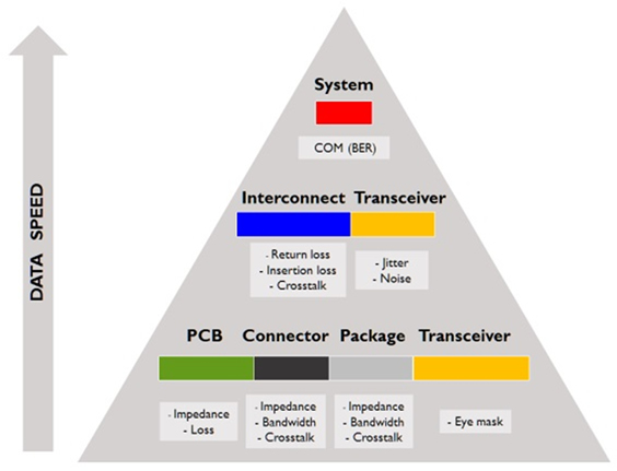
Design specification changes over time as data speeds increase. Slower systems were specified at the component level, but increasing interaction between components required system-level specifications. (Image courtesy Samtec Inc.)
A COM-type specification also allows consideration of signal processing in the transceivers. With increased levels of signal conditioning, more margin can be obtained, which again can be traded off with other components in the system. A COM specification allows significant cost/performance decisions early in the system design process.
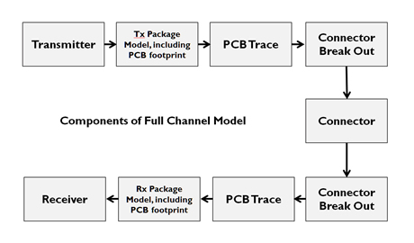
High-level schematic of component models included in a full-channel simulation (Image courtesy of Samtec Inc.)
In light of the many conflicting tradeoffs encountered when specifying a high-speed mezzanine connector, a system designer should consider talking with a supplier’s application engineer early in the design process. Such engineers are trained and experienced in connector selection, and they can provide a significant jump-start to the decision-making process.
Author Julian Ferry is principle R&D engineer at Samtec Inc.