Six Things to Consider When Specifying Electrical Connectors for the Mil/Aero Market
Adnane Jaghmim, Tests and Measures Manager; Thibault Monet, Design Engineer; and Nataliya Mayaki, Brand Manager, Nicomatic
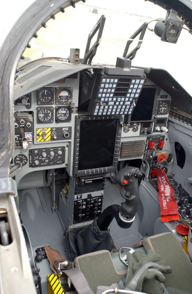
The interior of this T-38C Talon trainer features improved avionics and support systems that make it closer in design to fighter aircraft like the F-15 Eagle, F-16 Fighting Falcon, and F/A-22 Raptor.
Harsh-environment military and aerospace electronics applications require specialized interconnect solutions. The interconnect solutions for these applications not only have to withstand extreme environmental conditions, such as extreme operating temperatures, high vibration, high pressure, and exposure to water or dust, but must also correspond to the high level of technical performance demanded by the final applications. To attain these performance levels, specifying engineers need to take many things into consideration, especially: materials, technology and design, customization, method of integration, and the products’ use.
The military and aerospace markets encompass a wide variety of different applications, including: radar, cameras, vehicular electronics, avionics, embedded systems, UAVs, and many others. Despite their differences, connectivity is at core of all of the applications within these markets, and ensures both peak performance and reliable data transmission. As such, all of these applications require very high-performance and high-reliability components built to military or aeronautics standards, such as MIL-DTL-55302, MIL-DTL-83513, and EN 4165. The uniqueness of these varied applications can make connectivity choices very difficult for the engineers tasked with implementing them in different electronic systems and ensuring that they’re adapted to many criteria at the same time. Military and aeronautics standards like these help interconnect solutions providers offer standard, tailored, or custom solutions ideally adapted to each customer’s unique needs.
Environmental Conditions
The first thing to consider when choosing a mil/aero connector is the external environment in which the connector will be placed and which external elements, such as temperature, pressure, and moisture, it will likely confront.
Environmental temperature is a very important condition, because it has a direct impact on the connector’s technical performance and function. Connectors behave differently in different temperatures conditions. According to IEC 60512-5-2 Test 5b, a connector could allow 3A to flow through at 25°C, but only allow 2.5A at 85°C because, as current flows through a connector, it heats. So, connectors with lower operating temperatures can handle more heating and, as such, can carry higher current. For example, if a connector can sustain 125°C in continuous use, and its operating temperature is 25°C, it could withstand a temperature rise of 100°C. However, if the same connector’s operating temperature were 85°C, it could only withstand a rise of 40°C and thus could not handle as much current as the same connector in a 25°C operating environment. As such, it is important to consider operating temperature conditions and their potential effect on connector behavior and technical performance when selecting connectors for mil/aero applications.
Pressure is another important environmental condition to take into consideration, as it can also affect connector performance. Connectors in aerospace applications perform differently at sea level than at high altitude because the lower and higher pressures have different effects on their electrical properties. According to Paschen’s law, when a differential potential is applied between two contacts or between a contact and the shell, flashover may occur. This phenomenon creates a high-voltage electric short circuit through the air between exposed conductors and thus mainly depends on the distance between contacts and air pressure. In standard connectors, the breakdown voltage resulting from flashover creates a leakage current in the air that can damage the overall system and diminish its performance.
To account for pressure changes in a connector’s external environment, engineers should pay particular attention to a connector’s rated voltage, which is the voltage that can be applied during continuous use, as well as its withstanding voltage, which is the maximum voltage that can be supported by the connectors over a 60-second span; for example, when lightning strikes a plane and causes an overload voltage. If a connector’s withstanding voltage performance was rated at sea level, that value will vary at different altitude levels. At sea level, where the air pressure and density are high, higher energy (i.e., voltage) is needed to create a leakage current in the air. Alternately, at high altitudes, where the atmospheric pressure and density are low, less energy is needed to create a potentially damaging leakage current. The withstanding voltage for connectors with a fixed small pitch is also limited by altitude. So, to prevent connector damage in mil/aero applications exposed to environments with pressure differentials, as well as to increase performance at specific pressures, engineers have to both calculate the ratio between rated voltage, withstanding voltage, and breakdown voltage to define the right rated voltage and consider the distance between contacts.
Housing Materials
Housing materials are the second thing to consider when choosing a military connector, as various material properties will have different impacts on overall connector performance. The way in which different materials respond to environmental conditions, such as operating temperatures and exposure to chemicals or radiation, also plays a role in this decision, as does a connector’s position within an application, which can impact its exposure to external elements. For example, if a connector’s operating temperature is lesser than or equal to 110°C, its housing could be made of polyoxymethylene (POM); whereas, if its operating temperature is above 150°C, it would be better to use the polyphenylene sulfide (PPS) or liquid crystal polymer (LCP) materials. Housing materials can also impact the electrical and mechanical performance of connectors exposed to radiation. For example, for radiation levels equal to 150Mrad, PPS or Ultem/polyetherimide (PEI) materials are a better choice than polyamide (PA) materials, which can only withstand 0.5Mrad. Ultem/PEI materials are often chosen for space applications due to their high radiation resistance. These particular plastic materials can also be used to improve the chemical ingress resistance of polybutylene terephthalate (PBT) materials. Additionally, glass fibers can be added to plastic connector housing materials to improve their mechanical resistance and enhance rigidity.
Potential chemical reactions are another point to keep in mind when selecting housing materials. For example, an aluminum panel in electrical contact with a nickel connector shell and in the presence of an electrolyte can cause galvanic or bimetallic corrosion.
Raw material origins and their environmental impact are also important factors for connector housing selection. More and more connector manufacturers are pursuing sustainable development and reduced pollution and are offering REACH- and RoHS-compliant materials.
Technology and Design
The third thing to consider when selecting a mil/aero connector is its technology and design. Connectors are comprised of several different elements, each with different performance specifications. This can make it difficult for design engineers to combine all of the elements according to an application’s performance requirements, but they can work with connector suppliers to harmonize the specifications the various connector elements with the application environment and required performance to avoid the selection or creation of an overqualified connector product that will bypass expected performance, as well as the system budget. For example, using hyperboloid contacts, which are capable of more than 10,000 mating cycles, in an application that only needs a connector capable of 1,000 mating cycles connector is overkill, oversized, and will incur extra costs.
Another important point to consider is the number of contacts in a connector, as this influences the capacity of the connector to pass the current through it, according to the allowed temperature rise. Connectors with fewer contacts will pass more current than a couple with many contacts, as their temperature elevation will be higher and attained more quickly (See Figure 1). These aspects are described in connector manufacturer’s derating curves, which should be carefully considered in order to choose the connector that most closely corresponds to the performance requirements of the electrical system in a specific application.
Figure 1: A connector with two contacts can carry 12A at an average temperature elevation of 30.4°C, while a connector with 69 contacts under the same conditions can only carry 3A.
When designing for high-vibration environments, engineers should seek out contacts that employ clip technologies with multiple tabs, as these are more reliable in terms of signal continuity and integrity than a contact with only two tabs. If the requirement is high power transmission, the contacting surface between contacts should be as large as possible to make the power flow easily and reduce the resultant temperature rise that limits performance via derating. Engineers should also be sure to select contact designs and materials recommended by the connector manufacturers and guaranteed to deliver reliable mechanical performance.
Custom Design
The fourth thing to consider with regard to mil/aero connector selection is whether to choose a standard or customized connector. Custom connector designs are built to address the many specific physical requirements and performance specifications that an engineer may need for a particular application. Two of the main reasons to choose a customized connector are to address severe size constraints and to better integrate the mechanics of a connector into a system.
For example, if a customer needs to integrate two different types of connectors (e.g., signal and power) in a very small space, a custom solution can provide both groups of contacts in a single connector with performance-optimized spacing, saving the customer the board space that would otherwise be occupied by two different connectors. In such cases, custom solutions allow customers to reduce component size, optimize integration costs, and improve ease of use. Custom interconnect solutions like these can also provide a perfect match to military requirements and enhance the technical performances of the overall system.
Figure 2: This custom, double-way DMM harness by Nicomatic combines low-frequency signal contacts with high-power contacts in a compact, low-profile housing, meets mil-spec requirements, and delivers application-optimized performance.
In order to achieve the most suitable custom component possible, engineers should create a detailed technical scope that lists all of the desired property and performance specifications according to the application environment. A very detailed scope provides connector designers with a lot of technical constraints at the beginning of the project, which helps to ensure that the final product corresponds to all expected requirements. Such a scope may also contain material choice requirements. For example, if a mil/aero application requires a corrosion-resistant connector that also exhibits good electrical conductivity, an engineer could specify gold plating of a certain thickness. However, they should also keep in mind that upfront materials choices can impact the connector’s integration process into an electromechanical system.
Component Integration Process
The component integration process is the fifth thing to consider when choosing a mil/aero interconnect solution. There are many ways to integrate an interconnect solution in a system, and crimping is a popular one. The crimping process is comprised of four elements: crimping tool, positioner, crimping contact, and cable. Crimping tools mechanically define the crimping depth, positioners define the crimp height, and crimping contacts and cables come with manufacturer-recommended corresponding conductor and sleeve diameters. All connector manufacturers offer a specification for their positioners, as these allow customers to correctly crimp contacts and achieve secure interconnections in their application. IPC standards provide different criteria for validating the correct crimping and soldering processes according to the critical level of an application (i.e., its IPC class). In order to successfully crimp contacts and guarantee the expected performance of an interconnect solution, integrators should be sure to follow the IPC’s rules of integration. For instance, tensile strength tests allow integrators to validate the retention strength of the cable in a contact according to its gauge. The main advantage of the crimping process is repeatability, as this process can be used on all connectors in an electromechanical system once it is mastered. The downside is that this process is not very simple and requires several different steps for completion.
Many connector manufacturers offer contacts that can be integrated using several different processes, allowing customers to choose the most suitable integration process for their specific application. For example, some contacts can be crimped or soldered on a cable to provide engineers with more flexibility to adapt the interconnect solution to their unique process of component integration.
When terminating connectors to cables, it is also important to pay particular attention to cable selection. The same types of cable with the same gauge can sometimes have a different composition (i.e., a different number of strains in the cable) and different dimensions, which can seriously affect the integrated connector’s performance. The correct selection of all connector elements and assembly processes is critical for ensuring the long-term use of the complete interconnect solution.
Use of Connectors
The sixth thing and final thing to consider when selecting mil/aero connectors is their end-use. Harsh-environment connectors should be integrated with great care in order to ensure optimal performance. In fact, connector manufacturers typically recommend a specific torque for their harsh-environment connectors, and it is important to respect these recommendations to ensure optimal performance. If the torque is lower than recommended, it can reduce the connector’s shock and vibration resistance, which can damage the connection. Similarly, if the torque is higher than recommended, it can make the contacts and connector more fragile and susceptible to damage.
Manufacturer’s recommendations regarding stocking and packaging connectors are quite relevant as well. If not done correctly, these actions can pollute a connector and diminish its performance.
Electronic system designers and integrators have to take many criteria into consideration to ensure the high quality, reliability, and performance of harsh-environment mil/aero electronics systems. Connector manufacturers offer a wide range of mil-spec interconnect solutions that meet the demanding size, weight, and reliability constraints common to these applications, and are innovating all the time. The best ways to ensure the successful integration of mil/aero interconnect solutions are to follow connector manufacturer’s recommendations, to work closely with a connector supplier to specify a solution, or to enlist a connector supplier to create a custom design.

Recently posted:
[related_posts limit=”10″]