How to Specify and Select a Connector
The “Connector Basics” series from APEX Electrical Interconnection Consultants continues with a tutorial on how to specify and select a connector for a particular application.
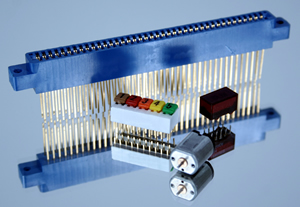 Generally speaking, electrical connectors are mechanical components that serve an electrical function. In addition to carrying electrical current at a specified voltage, connectors either enable interconnection of components during the assembly process or enable the user to easily disconnect and reconnect different parts of the equipment. The size and shape of connectors will vary based upon the electrical requirements of the equipment, the physical space within the equipment, and environmental conditions in which the equipment must operate.
Connector manufacturers typically catalog connectors based upon levels of interconnection, which refer to the connector application or mechanical method of interconnection. These applications range from connecting the chip to a circuit board to connecting peripherals to devices and beyond. Connectors that are attached to or mated with a printed circuit board comprise a large majority of catalog connector offerings.
Connector “Application”
The first logical consideration when specifying and selecting a connector is its application. This should occur as soon as practical in the design and development of the device in which the connector will be used. By starting early in the design process, it is more likely that the optimum balance of physical requirements, cost, and lead time can be achieved. If a customized connector is desired, the lead time will be longer than for standard catalog items. However, the customized or custom-designed connector may bring capabilities that enable the designer to meet specific performance or appearance requirements. The physical application configuration of the connector, including the method by which it is attached to the circuit board, is contained in the manufacturer’s data sheet or application drawing. Often CAD drawing files or 3D models are available to aid the equipment designer.
Electrical Requirements
The second consideration is the electrical requirements. These include current and voltage, but additional requirements such as RFI, EMI, shielding, signal speed, separation of power and signals, and grounding may also be considered. The number of contacts within the connector also needs to be specified. Since the electrical connector is part of the total electrical circuit, it may also be necessary to understand the maximum resistance that can be tolerated at the mating interface of the interconnection. One should understand how connector-related resistance may impact the application. Fortunately, this data is often available from manufacturers catalogs and data sheets.
Mechanical Requirements
The third consideration is the mechanical requirements. Some mechanical parameters, such as contact resistance, can affect electrical requirements. If the connector will be mated and unmated during the lifecycle of the equipment, the number of mating and un-mating cycles must be specified, as well as any minimum and maximum insertion or extraction force requirements. The ideal connector with zero insertion force and zero contact resistance does not exist. Much of the effort in the connector design process is devoted to approaching these ideal requirements.
Application Environment
The fourth consideration is the environment in which the connector will be used. This includes temperature and humidity extremes as well as any corrosive factors in the environment. If the connector must be sealed in some way, this requirement must also be specified. However, providing a description of the requirement rather than guidelines for how the requirement should be met will yield more choices for selecting suitable connectors.
Safety and Regulatory Requirements
The fifth consideration is safety agency approvals and environmental regulatory requirements. Government requirements include RoHS compliance. Safety agencies such as UL and CSA test products to ensure they meet the agency standards. Components such as connectors are usually “recognized” by the agency. Certificates of RoHS compliance are available from most connector manufacturers.
Manufacturing and Assembly
The sixth consideration is the manufacturing process, or how the connector will be assembled to a board or the contacts attached (terminated) to conductors. This includes thru-hole soldering or surface-mount reflow. The configuration of the contact is an obvious consideration, but the coefficient of thermal expansion, as well as the heat tolerance of the connector, is also important. In addition, there is a need to determine whether the connector will be assembled by hand or by automated pick-and-place equipment. The connector features and packaging will also affect the ease and ultimate cost of assembly. Some connector manufacturers will supply application tooling and equipment for their connectors. The ease of application and the cost of the equipment and service affect “the applied cost” of the connector. This applied cost includes both the purchase price and the costs incurred during the subsequent manufacturing processes.
Limits of Connector Product Specification
When selecting a connector, it is essential to respect and not exceed the limits of the connector product specification. For example, if wire terminations are used, it is important to stay within the limits of both the conductor sizes and the range of insulation diameters in the data sheets and product specifications.
If, at some point in the connector specification and selection process, a suitable connector cannot be found, there may be a need for a modified connector design or a new connector design. In the long run, this customized or new connector may provide better functionality, better reliability, and a better value to the customer. The disadvantage to the custom design approach is that longer lead times, more time and effort to interact with the connector company personnel, and a possible up-front expenditure for tooling and equipment will likely be required. The custom-designed connector implies that there might only be a single-source connector supplier.
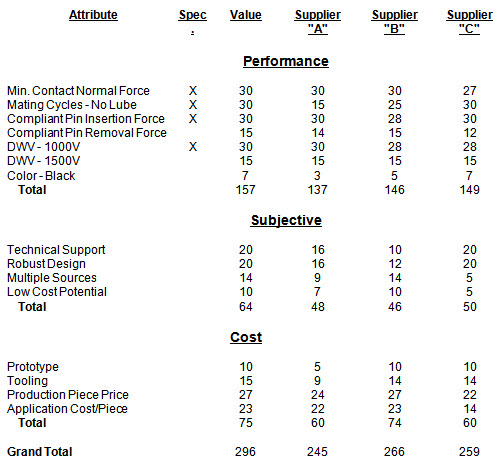
Hopefully at some point in the connector and connector supplier selection process, there will be more than one connector that has the potential to meet all requirements. A decision-making or prioritization matrix could be used for this purpose.
The criteria that are used should be identified as “must have/critical” or “want.” The “must have” specification will be assigned a weight of 30 and the “want” criteria assigned a lower rating. This analysis could eliminate one or more connectors from consideration. If the “must have/critical” issues are not satisfied, the connector would be eliminated from consideration. Selection of relevant attributes is essential to method of evaluation.
Risk Assessment
Depending upon how the criticality of the connector impacts system performance, a risk assessment may be appropriate. This risk assessment is best done by the project team, which should include a team member that has knowledge of electrical interconnections, preferably a component engineer. This risk analysis should also be included in the design review for the device or equipment.
A risk assessment analyzes the severity of the effects of connector failure modes. These effects and associated severity will be the same for all connectors under consideration. The next step is to document the potential failure modes and causes for the connector, as well as the probability of occurrence. This analysis is analogous to a Failure Modes and Effects Analysis (FMEA). However, detailed design dimensions and materials information are typically proprietary, and hence unavailable. The purchase of those connectors under consideration, as well as the mating components, will enable a firsthand examination. If automation will be used to assemble the connectors, a unit package quantity will help verify compatibility with the manufacturing process. More detail about how the connector actually works and even potential problems may be obtained from product engineers at the connector suppliers. The results of this risk assessment may also result in modifications to the electrical or mechanical design of the equipment in order to mitigate or reduce the probability of connector failure and the resulting impact to the overall system.
Therefore the connector selection process has three steps: 1) Determine and specify critical and desired criteria; 2) Prioritize criteria and evaluate these against offerings by each manufacturer; and 3) Assess and mitigate technical risks. As a result, connectors that should work in the application will have been identified.
On a broader level, again depending upon the criticality of the connector, it may also be desirable to evaluate the extent to which each supplier has the potential to meet all performance, cost, lead time, and service requirements.
[hr]
 With more than 30 years in the connector industry, George Bedorf has established a record of success with strategic planning and tactical implementation using process improvement methodology. He has expertise in the use of planning and tools to improve both business and manufacturing processes, as well as extensive hands-on experience in the development and implementation of new processes and the introduction of new products into manufacturing. Bedorf’s management experience includes director of quality assurance at AMP Incorporated. He has an engineering degree from Stevens Institute of Technology.
Visit APEX Electrical Interconnection Consultants online.
For more Connector Basics: