The Importance of Contact/Housing Retention
Never underestimate the importance of contact/housing retention mechanisms. Serious issues can arise if contacts are not assembled properly or if the retention device is not robust.
Connectors retain their electrical contacts within an insulating housing. Some retention mechanisms are more reliable than others. Serious issues can arise if the contacts are not assembled properly or if the design of the retention device is not robust.

Although some connectors are supplied to an end user with contacts pre-assembled in a housing (headers, surface mount tails, etc.), often the user must assemble contacts himself. Because this usually occurs after terminating conductor wires, it can affect connector performance, for better or worse.
Electrical contacts enable a separable, conductive path through a connector, and in effect extend the attributes of the primary conductors (wires, PCB traces, etc.). A housing physically separates, and electrically isolates, individual contacts while maintaining their orientation and spacing. This permits proper engagement and mating of the connector.
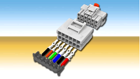
Contact retention features ensure proper axial contact positioning, facilitate assembly of the contacts and wiring/harnesses, and may allow the connector to be repaired. These features absorb contact mating forces and resist forces resulting from normal use of the connector (mating/unmating).
Retention features are generally designed for multiple uses (repairability) with the aid of insertion/removal tools that are specific to each type of connector.
Often, low-cost connectors suffer in terms of poor durability and inadequate contact retention features. However, connectors featuring highly effective contact retention mechanisms need not cost substantially more. It is wise to understand various retention methods, and even better to specify connectors having superior designs. As is frequently the case, the right retention design depends on the application.
Basic Types of Contact Retention Features
It’s common for contacts to incorporate some type of flexible (spring) feature that engages another feature (such as a step) within the circuit cavity of a housing. This resulting interaction essentially “captures” a contact within the connector housing.
First, there are stamped contacts. They often incorporate blanked and formed flexible retention features (or lances) as an integral part of the contact. These lances frequently take the shape of a simple cantilever spring, which can be curved, tapered, straight, or jogged, and generally extend away from the body of the contact.
Although adequate for many applications, performance of a stamped retention lance may be limited by the base material of the contact, since it inherently has the same properties and thickness. Its performance also depends on the integrity of an internal housing feature such as a shelf, notch, step, or ledge.
Stamped contacts can frequently be removed from a connector housing with simple tools (small screwdriver or probe), and sometimes may even be re-used. They may be identified by the presence of a seam along their length.
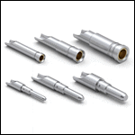
A second style involves a machined contact (made by precision turning of solid stock, such as by screw machining). These most often either have a separately assembled (stamped and formed) spring retention device or cooperate with a spring device contained within the housing.
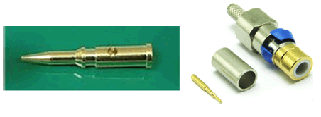
Machined contacts are characterized by a smooth external surface, frequently with steps or shoulders, and may or may not feature a flexible spring member, depending on whether the housing contains a spring.
The performance of a machined contact’s retention mechanism is generally superior to that of a stamped contact. In this case, a separate or assembled spring may be custom designed without being limited by the base material properties of the contact itself.
This type of retention feature normally requires the use of a specialized extraction tool, is robust, and may be reused a number of times. As a result, this type of contact retention device is often associated with high reliability (i.e. medical, military) and similar high-performance connectors.
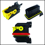
A third style of contact retention involves the use of various mechanisms that cooperate to secure contacts within a housing. These are sometimes known as terminal positional assurance (TPA) styles and are frequently encountered in automotive applications.
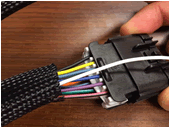
Essentially, this style of contact retention utilizes a combination of metal or plastic latches, along with other parts of the housing, to ensure that a contact is retained and fully seated within a housing.
Although the contacts associated with a TPA style of retention generally do not have spring lances, the associated housings often incorporate latching features that engage a step or other feature of the contact.
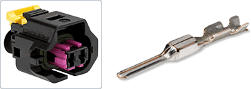
Additional housing components are designed to fit over the rear (wire-terminated) portion of the contact; these will only engage the housing if all contacts have been properly latched within the main housing. As a result, the contacts are retained, with visual and tactile assurance that all contacts have been properly seated.
Other types of contact retention methods include adhesives/potting; glass seals (hermetic); press-fit/interferences; trapped; insert-molded assemblies; and other combined or specialized methods. Although these are beyond the scope of this article, each offers advantages for particular applications.
Failure Mechanisms – Contact Retention
Contacts may fail to be retained and properly positioned within a connector housing for a number of reasons. Problems may relate to issues with the housing, contacts, retention components, or some combination. Issues can arise due to the presence of excessive forces, improper assembly, external damage, environmental conditions, abuse, and a host of other factors.
However, the most basic failure mode results from one or more contacts being out of position, or displaced (axially), relative to their mating counterparts. This partial or complete contact separation may result in an electrical intermittent or complete open-circuit situation.
Reasons for this type of failure may include:
- Complete pull-out: One or both contacts may have simply pulled out of the connector due to mishandling, lack of a strain relief, abuse, improper de-mating, etc.
- Partial push-back: Either contact may be moved rearward in the connector, without being completely dislodged, potentially a result of a stubbing situation due to connector or contact misalignment, improper initial assembly, damage to retention features, etc.
- Misalignment – cocking/tilting: Either the connectors or their contacts may have too much freedom of movement, such that the contacts are allowed to substantially misalign during mating. In severe cases, contacts can actually miss engaging each other but still may physically touch, appearing to be “OK” during a continuity test.
- Feature damage: Retention lances can be permanently bent, plastic housing features can be “skived,” and a material (metal or plastic) can be overstressed or even plastically creep with time, temperature, or other conditions.
Severe cases of contact retention failure can damage a connector to the extent that it becomes unusable, and it must be replaced. In very critical installations, failure of the contact retention mechanism may induce system failure, which can cause accidents, property damage, or loss of life.
Desirable Features
Regardless of the type of contact retention device, some features that are nice to have include:
- The ability to easily determine proper assembly with an audible snap or click or a visual confirmation feature
- Assurance that full seating has occurred with a slight “tug” or pull-back/wiggle test
- A fundamental design that is repairable, robust, and insensitive to reuse
- Contact features that resist handling damage (for example, bending or other damage due to snagging or tangling during harness manufacturing/assembly)
- Contacts that assemble to their housing with low installation force (which minimizes operator fatigue, buckled wires, etc.)
- Sufficient contact retention force, whether or not a wire strain relief is used
Other design, assembly, quality, and reliability attributes may be desirable depending on the application.
It is important to consider contact/housing retention features early in the design process, either during design of the actual connector or selection of a connector for a particular design application. Consider potential for damage during pre-assembly handling, as well as the adequacy of inspection and testing practices that address contact/housing assembly, and implement a strain relief at the wire-entry portion of the connector. Ensure that proper tools are available to repair/replace contacts.
An inadequate contact retention feature can lead to connector failure. Depending on the application, a high-reliability or even redundant design may be appropriate.
[hr]
 Ed Reynolds is a senior consultant at APEX Electrical Interconnection Consultants. He has more than 48 years experience with most aspects of interconnection products. Reynolds has experience in the computer, peripheral, telecommunications, automotive, consumer durable, consumer electronics, motor, transformer, small appliance, and power tool industries and held the titles of principal engineer and director of development engineering at AMP.
 Ron Locati is a principal consultant at APEX Electrical Interconnection Consultants. He has 31 years of connector industry experience, primarily in engineering and R&D. Locati led both technical and marketing efforts at AMP, was director of engineering at Augat-LRC Electronics/Thomas & Betts, and served as vice president of product development at Stewart Connectors (Insilco).
