Connector Basics: 3 Types Of Electrical Connectors
Do you know your connector basics? In this excerpt from the new book, “Electrical Connectors: Design, Manufacture, Test, and Selection,” two professors share fundamental knowledge about the principles of interconnect technology.
By Michael Pecht and San Kyeong electrical connectors
An electronic system is a hierarchical interconnection network that enables communication among different electronic devices. Several interconnects are required for the signal transmission and power distribution needed to ensure proper functioning of electronic devices. Electrical connectors are classified into three types based on their termination ends: board-to-board connectors, cable/wire-to-cable/wire connectors, and cable/wire-to-board connectors.
Six levels of interconnection are normally seen in electrical connectors. Level 0 is the connection between a basic circuit element and its lead, such as the link between a semiconductor chip and the lead frame. Level 1 is the connection between a component lead and a printed circuit board (PCB), exemplified by chip carrier sockets, dual inline package (DIP) sockets, and switches. Level 2 is the connection between two or more PCBs. A motherboard–daughterboard connection is typical. Level 3 is the connection between two subassemblies, such as a power supply and an associated subassembly. Level 4 is the connection from a major subassembly to the input/output (I/O) port of the complete system. Level 5 is the connection between physically separated systems typified by the link between a computer and a printer or other piece of peripheral equipment, or components of a local network.
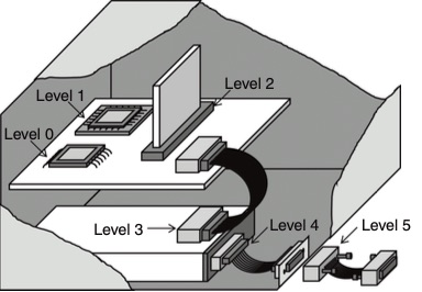
The six levels of interconnection typically seen in electrical connectors.
Board-to-Board Connectors
Board-to-board connectors are used to connect PCBs without a cable. The board-to-board connectors can save space on cables, making them suitable for systems with limited space. The PCBs can be connected using connectors in parallel or perpendicular configuration. A connector that connects two PCBs in a stacking configuration is called a mezzanine connector. However, the term is sometimes used to describe perpendicular or side-by-side PCB arrangements. These arrangements are usually seen for motherboard–daughterboard arrangements, where the focus is on the parallel arrangement.
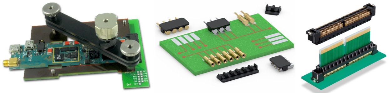
Custom board-to-board connectors from Ironwood Electronics (left), parallel board-to-board connectors from Mill-Max (center), and Hirose’s FX27 Series FunctionMAX floating, card-edge board-to-board connector (right).
The specifications that need to be considered when choosing a mezzanine connector include separability, mechanical requirements such as stack height and tolerances, constraints such as standoffs, brackets, or chassis slots and frames, and types of mountings. Separability is dependent on many factors, such as whether the connector is separable or permanent, the number of mating cycles required over its lifetime, and the maximum and minimum value of insertion force required. The operating temperature and humidity also should be considered. EIA 700AAAB is a standard for mezzanine connectors.
A backplane is a group of electrical connectors in parallel with each other so that each pin of each connector is linked to the same relative pin of all the other connectors, forming a connector bus. A backplane system is widely used in computer and telecommunication systems because of its flexibility and reliability. The backplane system is used for connecting multiple plug-in cards along a single backbone to make a complete backplane system. The signal generated by the transmitter passes through multiple connectors and reaches the receiver. A backplane system with high signal integrity is required in devices used in high-speed applications. In a gigabit backplane channel design, the backplane and the associated pin field are essential parameters.
As the data rate increases, the backplane channels can attenuate the transmitted signal. The channels cause inter-symbol interference (ISI), reflection, and crosstalk. Crosstalk and reflection introduce noise, decrease the signal amplitude, and degrade the signal edge rate, which further deteriorates channel jitter performance. At high data rates and long distances between channels, the signal integrity becomes worse.
The connectors for backplane systems should provide good impedance matching and shielding. The connectors also should withstand several insertion and removal cycles of circuit boards.
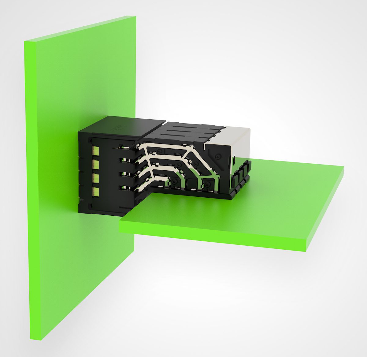
A backplane system containing TE Connectivity STRADA Whisper backplane connectors.
Wire/Cable-to-Wire/Cable Connectors
Wire-to-wire connectors connect two wires, as the name suggests. One end of the connector is permanently connected to the wire. The other end of the connector forms a separable interface. The permanent connection can be made using either crimping or insulation displacement contact (IDC). In the IDC method, connection is made by inserting the insulated wire into a slot of a sharpened metal beam. The sharp edges of the beam cut through the insulation and make a rigid metal–metal contact between the wire and the beam.
In the case of discrete wire connections, a crimping process is usually employed. However, in the case of multiconductor cable conductor termination, IDC is usually employed. This is because of the advantage an IDC offers with respect to wire handling and mass termination. Wire-to-wire connectors come in a wide variety of housing geometries, including rectangular and circular with polymer housings, made from a wide variety of polymers, and metal shells, primarily for military applications.
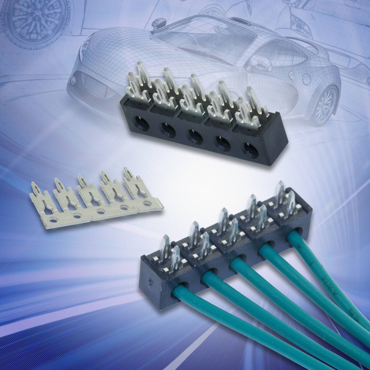
Designed for use in automotive applications, AVX Corporation’s 53-8702 IDC/Press-Fit WTB connectors combine IDC and press-fit connection technologies.
Wire/Cable-to-Board Connectors
A wire-to-board connector, as the name suggests, connects a wire/cable to a PCB. The wire connections are similar to the one used for wire-to-wire connection, and the board connections are, for the most part, press-in or soldered two-piece connectors, although some card edge versions remain in use. The mating interface for the separable connection may be identical to that of a wire-to-wire connector from the same product family. While there are many applications of wire-to-board connectors, the trend is toward cable-to-board connectors, or cable assemblies, to take advantage of the benefits of IDC.
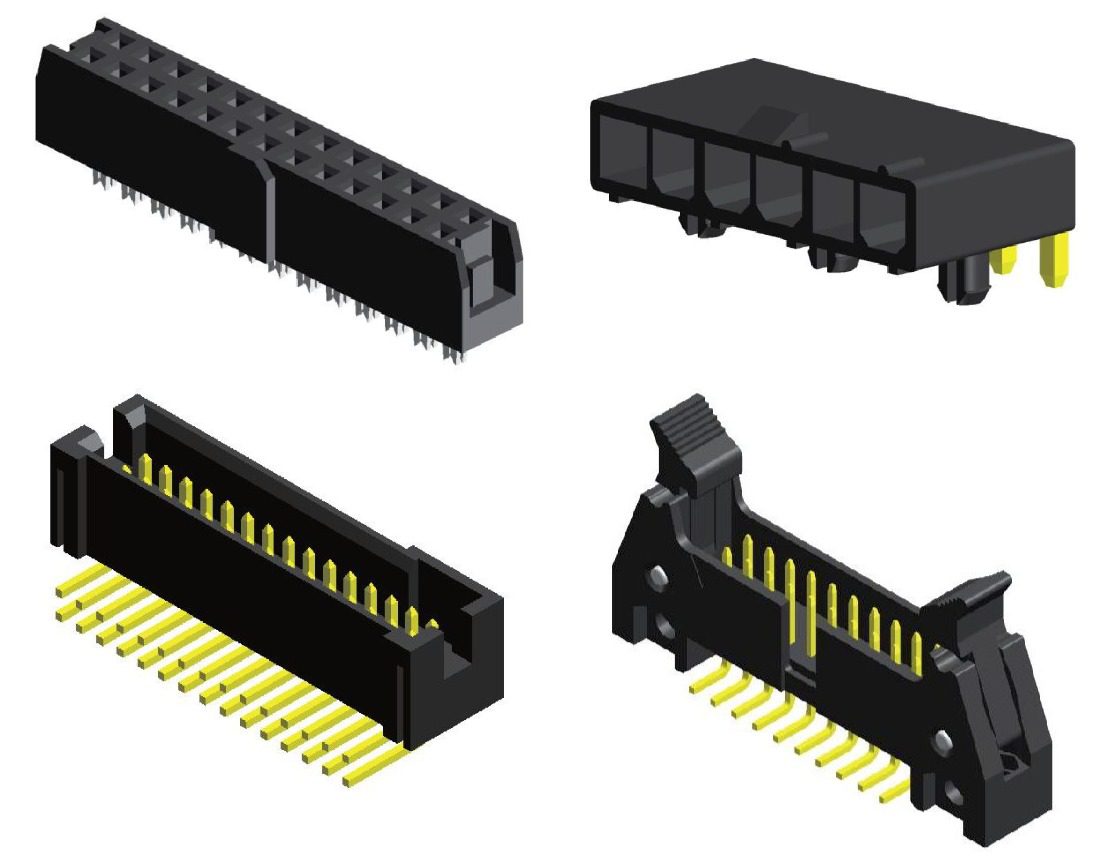
This set of custom wire-to-board connectors from Greencon displays a variety of unique housing configurations designed to serve tight automotive architectures.
Copyright John Wiley & Sons Limited, 2021, Electrical Connectors: Design, Manufacture, Test, and Selection, San Kyeong and Michael G. Pecht (Editors), 9781119679769.
This article is an excerpt from the new book, “Electrical Connectors: Design, Manufacture, Test, and Selection,” which covers everything one would need to design, manufacture, and select a connector for any targeted application. It includes the science of contact physics and the engineering involved in the choice and manufacture of contact materials, contact finishes, housing materials, and the full connector assembly process. Test methods, performance and reliability concerns, and guidelines are provided, and various application requirements and selection considerations are discussed.
Michael Pecht is the Director of CALCE (Center for Advanced Life Cycle Engineering) and a Chair Professor at the University of Maryland. He is an IEEE Fellow, an ASME Fellow, and an SAE Fellow. San Kyeong holds a post-doctoral position at CALCE the University of Maryland and is a staff engineer at Samsung Electro-Mechanics.
Like this article? Check out our other materials, contacts, and Connector Basics, and our 2021 and 2020 Article Archives.
- Engineering’s Future is AI-Inspired, Human-Led - June 23, 2026
- How High-Reliability Connectors Meet the Demands of Satellite Engineering - June 23, 2026
- Solar Energy for Remote Industrial Automation: Efficiency Off the Grid - June 16, 2026