Connector Degradation Mechanisms – Wear
Connector Degradation Mechanisms – Wear
This is the fourth article in a series on connector degradation mechanism, and it addresses connector wear mechanisms and processes. The previous three articles in this series discussed corrosion as a connector degradation mechanism; fretting corrosion in the case of tin contact finishes and general corrosion due to exposed base metal in noble metal contact finishes. This article will discuss an indirect degradation mechanism—wear of the contact finish. Wear is an indirect mechanism in that the wear process can lead to exposure of the base metal of the contact spring and that, in turn, can result in corrosion and contact resistance degradation as discussed in the last article.
There are two primary mechanisms that cause wear in connectors. The most obvious one is the wear that occurs each time the connector is mated, and the plug and receptacle contact surfaces slide against one another. The second mechanism is wear that occurs due to fretting motions during the application life of the connector. Fretting motions were discussed in the second article with the focus on fretting corrosion in tin finishes. As a reminder, fretting motions are small-scale motions, a few to a few tens of microns, resulting from mechanical disturbances or thermal expansion mismatch forces.
First, let’s address a few general comments on wear. Wear mechanisms can be very complex, so this discussion will be limited to some simplified, but generally appropriate, comments on wear processes in connectors. Wear can be described in a simple equation, though the meaning of the parameters in the equation can be rather complex.
V = k F L/H (Equation 1)
Where V is the wear volume—the volume of metal removed from the interface during a single wear event—k is the wear coefficient, F is the applied load—in the case of connectors, the contact force—L is the length of motion of the wear event, and H is the hardness of the metals in contact.
The interpretation of F, L, and H is relatively straightforward. The contact force, F, is a connector design parameter. The length of the wear event is the engagement length during mating, or the length of a fretting motion, depending on when the movement occurs. Engagement length is a connector design parameter, but the length of fretting motions is a variable dependent on many parameters. In the equation, H is the hardness of the metals in contact. For like materials, it would be the hardness of the given material. For two different metals, it would be a composite hardness. In connectors, the two contact springs generally have the same surface finish, say gold, but the thickness of the nickel underplate, and the hardness of the contact spring materials may be different, so a composite hardness is appropriate. For a given connector, however, F, L, and H can be considered, sort of, as “knowns.”
The wear volume, V, requires some interpretation. The parameter of interest in connector wear is the loss in finish thickness during each wear event. Given V = At, where A is the area of the contact interface and t the thickness of the material removed, t depends on the contact geometry. This dependence is obvious when you think of the wear due to a needle point in contact with a surface, in comparison to a one centimeter diameter ball bearing. Again, for a given connector system this relationship can be considered, again, sort of a “known.”
But k is a variable with many parameters. Among the most important parameters are the contact force, F, the hardness, H, the contact geometry, the surface roughness, and the state of lubrication of the surfaces in contact. Once again, F, H, contact geometry, and surface roughness are, sort of, “knowns” for a given connector. For connectors that are not provided in a lubricated condition, the state of lubrication is a variable dependent on the environment in which the connector is used. I suggest that, practically speaking, the contact force is the most significant parameter in k for connectors for the following reasons.
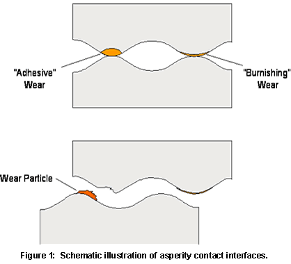
 Consider Figure 1 schematically illustrating two surfaces in contact. Recall the comment in the first article that, on the microscale of the contact interface, all surfaces are rough. For simplicity, two contact points, or asperities, are shown. In the following discussion it is assumed that the first contact creates the interface on the right, IA, in Figure 1, and as the load continues to increase, the interface on the left, IB, comes into being.
Under these conditions, IA experiences more deformation than IB. Given that asperity contacts are very small, the deformation will be plastic, and radial flow of the asperity will occur as the top of the asperities flatten against one another. This radial flow disrupts surface films and contaminants and helps to create the desired metallic contact interface. The metallic interface created will experience some degree of cold welding. Let me simply state that “cold welding” means that the metal surfaces in contact bond to one another across the asperity interface in the same manner that metallic bonds are formed in the interior of the metal. The metal of the asperity is also work-hardened due to the deformation of the asperities. The same processes occur as IB is created, but to a lesser extent. This means that interface IA will be much stronger than interface IB, because the larger amount of deformation has created a larger contact area for cold welding, and also experienced a greater degree of work hardening.
Given these interface characteristics, what happens when a shear stress is applied to the system? Because IA is the stronger interface, the applied stress must be sufficient to break the interface at IA and the weaker interface at IB will follow. From a wear viewpoint, the location where the interfaces break is important. Consider the state of interface IA. It is cold-welded and work-hardened. In fact, due to the work hardening, IA may have a higher cohesive strength than the base metal itself, and separation of the asperities may take place within the base metal, as shown in Figure 1, rather than at the interface. The resulting wear particle is the wear volume, V, cited in Equation 1. The weaker interface at IB may break at or near the original interface with little wear taking place. The wear process at IA is commonly referred to as adhesive wear, and that at IB as burnishing wear. If wear tracks produced during connector mating are viewed under magnification, say 30 to 50 magnifications, adhesive wear tracks will show evidence of wear particles and appear somewhat rough, while burnishing wear tracks will appear smooth and shiny.
Now back to k. Clearly, a change in wear mechanism, from burnishing to adhesive wear, will be reflected in a significant increase in the value of the wear coefficient k. The increase in k will not be continuous. Over some range of contact force, k will increase significantly. The magnitude of contact force resulting in the change in k will be dependent primarily on the state of lubrication of the connector. For clean surfaces, the transition range will be of the order of a few to tens of grams, while for well-lubricated surfaces, the transition may not occur until forces of hundreds of grams.
I hope you found this discussion interesting, but there is also a point. Adhesive wear processes will result in wear through of the plating finish with fewer wear cycles than burnishing wear. Once the contact finish is worn through, the base metal of the contact spring will be exposed and can then serve as a corrosion site and lead to contact resistance degradation as described in the last article. Adhesive wear is promoted by high contact forces, “sharp” geometries, and unlubricated surfaces.
Wear issues are, of course, best addressed in the design and manufacture of the connector system. Because wear rates vary inversely with hardness, tin-finished connectors will show higher wear rates than gold connectors. This relationship also indicates why so-called hard golds are typically used. Another design parameter of importance to wear in gold-finished connectors is the nickel underplate, as discussed in the previous article. The thickness of the finish influences the number of wear cycles a connector can support without wear through. This factor should be accounted for if thin or flash gold finishes are being considered. If a connector system is found to be inadequate with respect to wear performance, a contact lubricant may be able to enhance performance sufficiently to meet application requirements.
- Nanocrystalline Silver Alloy Contact Finishes in Electronic Applications - April 6, 2015
- Nanocrystalline Silver Contact Platings - March 16, 2015
- Dr. Bob on Gold Flash Contact Finishes (and Max Peel) - September 22, 2014


