Reduce Risk in Medical Devices
Managing creepage and clearance is one design strategy that can help reduce risk in medical devices and systems.

How to Reduce Risk in Medical Devices
Medical equipment used to diagnose, treat, and monitor patients, such as electrocardiographs (ECGs), thermal cauteries, and monitors, has to meet extremely high safety requirements. The international standard IEC 60601-1 guides product designers on critical matters, including protection from electric shock, resistance against thermal and mechanical stress, risk management, and other considerations.
Whether medical products are used in medical facilities or in mobile applications including the patient’s home, reliable and robust components are a basic prerequisite to ensure continuous performance, maximum reliability, and intuitive handling. IEC 60601-1 obligates manufacturers of medical electrical equipment and systems to ensure that they are completely fail-safe. Specifically, this standard requires connectors and other components that handle the transmission of electrical power, data, and signals to provide protection against electric shock in point-of-care scenarios where medical devices come into contact, or could come into contact, with a patient or operator.
Safe Proximity
Today’s high-performance medical electrical equipment is part of nearly every healthcare environment. Because these are normally connected to the public electricity supply network, these products pose a latent risk for patients and operators. In these networks, power is transmitted at voltages ranging from 230V to 250V and at 50Hz AC, which is capable of triggering cardiac irritations. In addition, lightning strikes both to and near cables can lead to dangerous temporary overvoltages. As such, electrical equipment and systems used in the medical sector must be well protected.
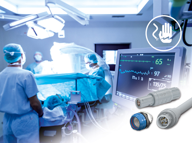
ODU MEDI-SNAP® connectors comply with the IEC 60601-1 standard.
The technical requirements stated in IEC 60601-1 relate almost exclusively to protection from electric shock. In order to reduce this risk as much as possible, the standard for medical electrical equipment and systems stipulates means of protection (MOP). These are subdivided into two categories: means of patient protection (MOPP) and means of operator protection (MOOP). Means of protection refer to the general precautions taken to protect people from electric shock as a result of a dangerous voltage when touching a medical device. IEC 60601-1 requires that two means of protection (2 MOPP and 2 MOOP) from electric shock — for both patients and operators — must be applied in electrical medical equipment and systems to ensure that if one means of protection fails, the other takes effect. One effective way to achieve this is to double the clearance and creepage distances between conductors.
Because patients frequently have a weaker constitution than medical personnel and may not be able to react (for example, if they are under anesthetic), they must be particularly well-protected. Therefore, the requirements placed on measures for patient protection are even more stringent than those for operator protection. Accordingly, the connectors used in devices designed to come into contact with patients, or that could by chance contact patients, require higher clearance and creepage distances, stronger insulation, and reduced leakage currents to satisfy 2 MOPP specifications. For medical electrical equipment and systems not located in patient environments, measures for the protection of medical personnel (2 MOOP) are sufficient.
Considerations for Connectors
To guarantee the means of protection involving a connector’s role in a medical product design, component designers must increase the clearance (the shortest distance between two contacts outside the solid insulation) and creepage (the shortest distance between two contacts along the surface of an insulation body). Clearance distances collapse as soon as the voltage becomes too high for the distance between two contacts. If these clearance distances collapse due to an excessively high field strength, electric arc flashes occur and can damage individual components, such as connectors, as well as endanger patients and operators. Creepage distances, on the other hand, tend to deteriorate gradually due to causes including dirt and dust deposits on the insulation body, or moisture, which precipitates onto the insulation body due to significant changes in temperature. These elements can lead to a partial or complete loss of a connector’s insulating function, result in the flow of leakage currents, and create an electric shock risk for patients and operators.
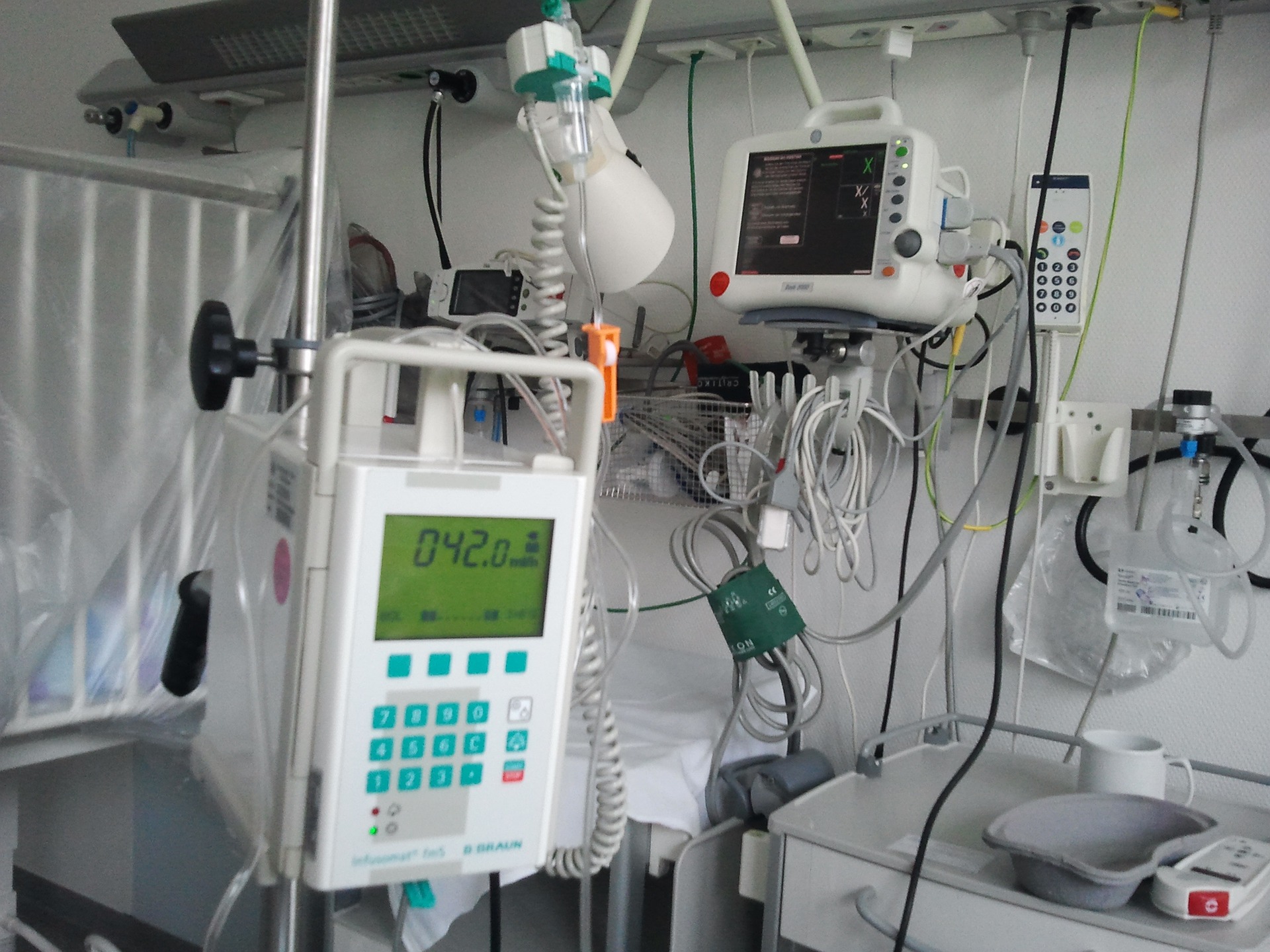
Hospital equipment must protect patients and providers from electrical shock.
Connector manufacturers can design creepage and clearance distances in such a way that they can master the respective voltages rather than lie victim to them. For example, in a Schuko plug commonly used in Europe, the two contact pins are set approximately 15mm apart from each other. Consequently, there are hardly any design challenges or shock risks when transmitting 230V with these connectors. However, if the same voltage were to be transmitted using a circular connector on which the pins were set only 1mm apart, it becomes a substantial design challenge due to the risk of clearance collapse.
One solution is to extend clearance and creepage distances by integrating labyrinthine geometries into the shape of the insulation body. For this purpose, domes made from plastic are added to the insulating body of the male connector to allow for a partial enclosure of the contact pins. Insulating collars can also be formed around the socket contacts within the insulating body of female connectors to match the domes. These design elements prevent the contacts from being connected in a straight line when mated, achieving higher clearance and creepage distances and offering maximum protection.
In addition to the use of domes and insulating collars, it is possible to arrange the contact pins asymmetrically. For example, a multi-position connector can transmit higher voltages with six high-voltage contacts placed further from each other than the other six signal transmission contacts. Accordingly, the contacts intended for the high-voltage transmission are separated by a 3mm distance and have an appropriately higher clearance and creepage distance than the ones used for signal transmission, which are set apart by only 1mm.
A third option is to design in additional insulating sleeves. These can be pushed over one or more contacts on the connecting side of a circular connector. Depending on the installer’s preference, this can be done either before or after soldering. In a similar manner to the labyrinthine arrangement, these sleeves extend the distances between the contacts and thus improve the electric insulation.
It is also possible to implement two of the means of protection stated in IEC 60601-1 into several separate components within the electrical medical equipment. Designers could, for example, integrate one means of protection into the power supply and a second within the connector. Such protections have to be verified by manufacturers during the approval procedure, so it is imperative that manufacturers and suppliers collaborate closely during the development of new medical electrical equipment and systems.
By Alexandra Fuchshuber, Product Manager, MEDI-SNAP, ODU Connectors
Like this article? Check out our other 2019, Medical Market, Standards, and Connector Basics articles.
How to Prevent EMI When Designing an Interconnect Solution for Medical Devices
- Four Essential Sensors - June 9, 2026
- Niobium and Tantalum Power the Next Generation of Technology - June 2, 2026
- Fortifying Connectivity: The Essential Role of Ruggedized Connectors in Extreme Applications - May 26, 2026