Power Contacts and Connectors Part 1 – Power Distribution
Power Contacts and Connectors
Part 1: Power Distribution
Today, there are three different approaches to power distribution in connectors, particularly, on current distribution. They include individual high-current contacts, multiple low-current contacts in parallel, and hybrids, which use both approaches in the same housing. Each approach has its advantages and limitations. Let’s begin with high-current contacts, or contacts capable of carrying multiple-tens of amperes.
The advantage of dedicated high-current contacts is that one contact is used and the rated current capacity for that contact is on the data sheet. (Recall that the test program and qualification criteria must be the same for all contacts being considered to ensure the rated currents are equivalent.) No allowance for thermal interactions among multiple signal contacts in parallel is necessary (we’ll address that condition in the next article).
Dedicated high-current contacts are limited by contact size and termination methods. The size consideration comes from the need to reduce the contact bulk resistance. Recall that there are three sources of resistance in a connector, the resistance of the permanent connections, the bulk resistance of the contacts themselves, and the contact interface resistance. In a signal or low-current connector, the bulk resistance is generally the dominant contribution to contact resistance. The message, then, is that a high-current contact requires that the bulk resistance be reduced significantly. The reason for that is Joule, or I2R, heating, which of course, is more pronounced at high currents and drives many of the design and materials decisions for power contacts and connectors.
The bulk resistance depends on two factors: the conductivity and geometry of the contact spring members. With respect to contact geometry, increasing the cross-sectional area of the contact will reduce the contact resistance, which is why high-current contacts tend to be larger than signal contacts. The conductors to which the contacts will be terminated will, of course, also be larger, for the same reason. This increase in size is a limitation of dedicated high-current contacts.
The bulk resistance also depends inversely on the conductivity. A change to a higher conductivity spring material will reduce the bulk resistance. For example, a change from cartridge brass (CDA 26000 with conductivity at 26 percent IACS) to copper (CDA 11000 with conductivity at 101 percent IACS) will reduce the bulk resistance by a factor of four.
Permanent connection resistances will also be reduced because of the increase in contact and conductor size and the accompanying increase in contact area. However, it is important to ensure that the contacts themselves are properly sized for the conductors. If the contacts are to be used in a range of wire or bus bar sizes, they should be capable of carrying the current of the maximum conductor size in the range. The termination method may also be more problematic, as contact and conductor sizes increase and require higher termination forces, e.g. crimped connections, or bolted components, which is also a limitation of dedicated high-current contacts.
Contact interface resistance performance can be improved in two ways by increasing the contact force. First, by increasing the contact area, and therefore, reducing the magnitude of contact resistance, as schematically shown in Figure 1; and second, by increasing the stability of the contact resistance due to enhanced friction forces at the contact interface. These benefits are compromised, however. The decrease in resistance becomes incremental at high contact forces, as shown in Figure 1. Also, enhanced friction forces will increase mating forces, and increase the wear on the contact interface during mating. These negative factors can be reduced by using multiple contact beams.
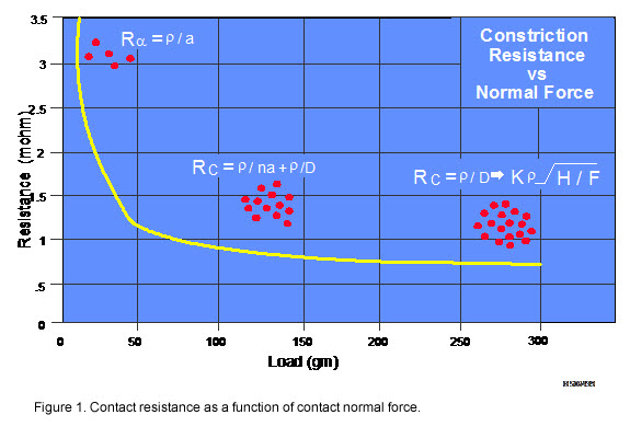 The following example is highly simplified, but does represent real performance improvements that can be realized by multiple contact beams compared to a single high force contact beam. Consider a single cantilever contact beam with a contact force of 600 grams. For the purposes of this discussion, assume that an extrapolation of the data from Figure 1 to 600 grams indicates a contact resistance of 0.5 milliohms. Assume that the single 600 gram contact force beam is replaced by four 150 gram contact force beams. From Figure 1, the contact resistance at 150 grams is taken as 0.8 milliohms. Because the four beams are electrically in parallel, the resistance of the new contact configuration will be 0.2 milliohms—a significant reduction in contact resistance. But there are additional benefits.
With the reduction in normal force, the wear mechanism of the contact interface will probably change from adhesive to burnishing wear, a change that will also result in a reduction in the coefficient of friction. The change in wear mechanism will increase the mating durability of the contact interfaces. The change in the coefficient of friction will reduce the mating force. Thus, the four-beam contact system will have reduced contact resistance, reduced mating force, and improved mating durability.
What about the stability of contact resistance? The electrical redundancy of four contact beams compared to one provides enhanced contact resistance stability. Certainly the mechanical stability of any one of the reduced force beams is less than that of the high force beam. But contact redundancy outweighs the loss in mechanical stability. Consider two cases. First, two of the four beams could go open and the contact resistance of the system would go from 0.2 to 0.4 milliohms, still below the 0.5 of the single beam system. Second, consider uniform degradation of the four contact beams. If each beam increased in contact resistance by an order of magnitude, from 0.2 to 2 milliohms, a significant degree of degradation, the contact resistance of the four-beam system would be 0.5 milliohms, the same as the original resistance of the single beam system. This is the power of contact redundancy.
For completeness, it is worth noting that redundancy is also the source of the resistance stability of the contact interface itself. Figure 1 shows multiple contact spots due to the microscale roughness of the surfaces of the plug and receptacle contacts. Loss or degradation of a number of these individual contact points will not significantly affect the resistance of the contact interface, as long as it remains mechanically stable. Motion of the contact interface due to mechanical or thermally generated stresses is the driving force for contact resistance degradation.
This discussion explains the reason that most high-current contacts use multiple redundant contact beams. The high-current bus bar connector shown in Figure 2 provides a good example. The separable connection contact system consists of six independent contact beams, three on each side of the bus bar. These beams, of course, provide all the benefits of redundancy discussed above. There are three permanent connections in the system, the crimped connection between the conductor and the ring contact, the bolted connection between the ring contact and the bus bar connector, and a dual redundant bolted connection between the bus bar connector and the bus bar. The thickness of the contact beams, given that contact force depends on the thickness cubed, indicates that each contact beam has a significant contact force. Notice, too, the enhanced mechanical stability provided to the contact system by the anti-rotation beams. Finally, and not visible in Figure 2, is the silver contact plating, a preferred choice in power contacts, as discussed in previous articles in this series.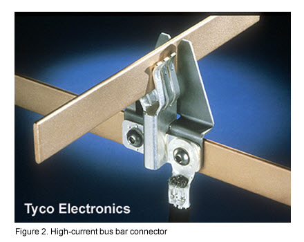 In summary, the design of high-current contacts, several tens of amperes, requires reduction in contact bulk resistance and enhanced contact resistance stability. The reduction in bulk resistance is generally accomplished by using larger contact cross sections, and, in many cases, higher conductivity contact materials. The enhanced mechanical stability can be provided in two ways, by very high contact force systems, and by multiple redundant contact beam systems where contact redundancy reduces the magnitude of the contact resistance as well as enhancing contact resistance stability.
In many cases, multiple high-current contacts with lower current capacities and a few tens of amperes are used in parallel to provide higher current capacity. In such cases, the considerations that will be discussed in the next article, “Power Distribution II – Signal Contacts in Parallel,” will apply.
- Nanocrystalline Silver Alloy Contact Finishes in Electronic Applications - April 6, 2015
- Nanocrystalline Silver Contact Platings - March 16, 2015
- Dr. Bob on Gold Flash Contact Finishes (and Max Peel) - September 22, 2014