Power Distribution II – Signal Contacts in Parallel
Power Distribution II
Signal Contacts in Parallel
This is the final article in our series about the distribution of current in power applications. In the previous article in this series, the topic was distribution of current using dedicated high current, several tens of amperes, contacts. This article will address the use of multiple signal—low current, a few amperes—contacts in parallel to distribute the current.
Despite the low current rating of such contacts, Joule heating is still a driving concern. This is because the current rating for the contacts is based upon a 30-degree T-rise over ambient at rated current. (Read more about this in part one of the series.) Signal contacts are typically smaller than high-current contacts, and will generate less heat at the 30-degree T-rise, but the increased number of contacts still warrants concern for thermal interactions among the contacts. The concern is that an increased temperature rise at each contact results in a positive feedback loop because the contact bulk resistance increases with temperature. These thermal concerns mean that the current rating of a contact must be derated when multiple contacts are used in parallel to distribute current. Three factors affect the current derating: the number of contacts, the distribution of the contacts in the connector housing, and the current distribution among the contacts.
Consider the last factor first. The ideal case is for all contacts to carry the same current so that they will all be at the same temperature. This, essentially, is the definition of contacts being in parallel. This means that the resistance across the complete circuit for each contact is the same. There are two sources for variation in the circuit resistances: internal variances among the contacts and external circuit variances.
Internal variances include variances in the contact interface, permanent connection, and bulk resistances of the contacts. While there is little doubt that variances in contact interface and permanent connection resistances exist, those variances are expected to be small. That is also the case for bulk resistances, with one important exception: right-angle multi-row printed wiring board (PWB) connectors. The “preferred” distribution, from the PWB point of view, is to cluster all the current-carrying contacts in one section of the connector for ease of feeding the current from the power/ground planes to the connector contacts. For a right-angle connector, however, this introduces a different bulk resistance for each row of contacts, and therefore, an unequal distribution of current among the contacts, all other circuit elements being equal.
Examples of external variances include splitting of a cable so that different cable lengths go to different boards performing the same function, or equal cable lengths going to different functions, with different power requirements, on the same board. In either case, the current distribution among the contacts will not be uniform. While simple in principle, these potential pitfalls are not always taken into account.
The effects of the number of contacts and the distribution of the contacts in the housing will be considered simultaneously. It is assumed in this discussion that parallel circuits have been realized and all contacts carry the same current. The concern about the number of contacts in use is obvious—the greater the number of contacts, the greater the heat generated. The distribution of contacts determines how much of the heat generated couples into nearby contacts. The importance of this consideration depends on the design of the connector housing, and whether the contacts are shielded from one another by internal housing walls, or have a “line of sight” path in an open housing configuration. Obviously, the coupling will be higher with an open configuration. Clearly the lowest coupling would occur with the contacts uniformly distributed as far away from one another as possible, over the housing. This configuration, however, is difficult to implement, especially in a PWB application where the power-carrying contacts would be clustered on a power or ground (power return) plane.
The following example provides some insight into these issues. The connector system in the example consists of pin/socket crimped contacts snapped into a 12-position housing. The contact can be used for three different wire sizes, as indicated in Figure 1. The contact current rating, when crimped to the largest wire, is normalized to unity in the figure. (It is assumed that the contact current rating has been determined by an End-Of-Life current rating process, as described earlier in this series) Note that in a single contact configuration, A, the contact current rating must be derated when the contact is crimped to the smaller wire sizes. Two factors contribute to this derating. First, the heat generated by the conductor at a given current will be higher due to the increase in conductor bulk resistance as the conductor size decreases. Second, the heat sinking capacity of the conductor will decrease as the conductor size decreases, because the thermal conduction will decrease with conductor size and the temperature of the conductor will be higher, reducing the delta T between the contact and the conductor. The combination of these two effects means that the temperature rise at the “hot spot” on the contact used to current rate the contact will reach the 30-degree centigrade limit at a lower current, as conductor size decreases.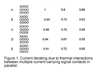 Figure 1 also shows the various positions in the housing, with “x” indicating a current-carrying position and “o” a signal position. The derating, due to thermal interactions when two and three contacts carry current, is shown in B to E. Consider now the data for the contacts crimped to the largest conductors. For two contacts in adjacent positions, the thermal coupling between the contacts will be maximized, and a seven percent current derating is appropriate. When the contacts are spaced as far apart as possible in the housing, the derating is only two percent. For three current-carrying contacts in adjacent positions, the derating is 16 percent, and when widely separated, the derating is nine percent. The increase in derating of the three adjacent contacts is due to two effects. Initially, the same current flows through each contact. The center contact, however, has heat input from the contacts on both sides and will experience a larger increase in temperature than the outside contacts. The accompanying increase in the bulk resistance of the center contact will result in a decrease in the current through that contact and an accompanying increase in the current in the outside contacts, another positive feedback loop. The end result is a current derating to maintain the T-rise requirements on the contacts. This same feedback loop is accentuated as additional current-carrying contacts are added to the housing.
Now consider how this derating for thermal interactions affects the number of contacts needed to carry a given current. Say the current rating for the individual contacts, terminated to the largest conductor, is three amperes, and the current to be distributed is 15 amperes. The initial number of contacts required would be five. In this example, the derating for the 12-position housing with six current-carrying contacts evenly distributed in the housing would be 18 percent (not shown in Figure 1), so the effective current rating of the contacts is 2.5 amperes, and the number of contacts needed would be six.
It is important to note that the derating factors in the figure are intended to indicate trends due to thermal interactions. The magnitude of the derating is dependent on the wire/conductor size, which is the current capacity of the contacts and conductors, and the pin count and configuration of the housing. Higher current capacity contacts will show a stronger effect of thermal interactions because of higher Joule heating. High loading of the housing with current-carrying contacts will incur a significant thermal interaction derating penalty.
One advantage of using multiple signal contacts in parallel to deliver high currents is the ability to use a single housing with an appropriate pin count to accomplish both power and signal distribution. This basic advantage has been further optimized by the development of hybrid power connectors, connectors where both power and signal contacts are contained within the housing. Hybrid power connectors minimize the thermal interaction “derating” by using a smaller number of high-current, 30 to 60 amperes, contacts.
- Nanocrystalline Silver Alloy Contact Finishes in Electronic Applications - April 6, 2015
- Nanocrystalline Silver Contact Platings - March 16, 2015
- Dr. Bob on Gold Flash Contact Finishes (and Max Peel) - September 22, 2014